Postprocessor functions
Important
Postprocessor functions are done at the main calculation of the channels.
Attention
Instead of temporary channel C1, a channel name can be used for creating a permanent channel!
Attention
#CH stands for #Channel!
Additional formulas
Integer formula
The integer formula can be used to subsequently adjust a channel, if it was not set correctly before measurement.
The formula is given by:
Syntax |
Meaning |
|---|---|
C1=F(#CH, I(Multiplicand,Divisor,Offset)) |
#CH is linearized with the respective parameters and outputted with channel #C1 |
Attention
Parameters are integers!
Important
Parameters can be channels as well as constants
Important
Use command if zero position was not set correctly at recording
Important
Use command if channel calibration was not set correctly at recording
Real formula
The real formula can be used to subsequently adjust a channel l, if it was not set correctly before measurement
You can use any channel as parameter of the function. The formula is given by:
Syntax |
Meaning |
|---|---|
C1=F(#CH, R(Factor, Offset)) |
#CH is linearized with the respective parameters and outputted with channel #C1 |
Attention
Parameters are floats (single)!
Important
Parameters can be channels as well as constants
Important
Use command if zero position was not set correctly at recording
Important
Use command if channel calibration was not set correctly at recording
ChannelArray
The command ChannelArray was implemented to prepare output channels for rotation and then only need one command line for the actual rotation command. This reduces input errors of the user because the parameterization of the command is much clearer.
Attention
The rotation commands Rot_3D_… and Madgwick_AHRS IMU need prepared channels!
Syntax |
|---|
C1=ChannelArray(‘Name_VAR1’, ‘Name_VAR2’, ‘Name_VAR3’) |
Meaning |
Preparing the output channels for a subsequent calculation which expects prepared output channels. |
Important
The by ChannelArray created channels are not saved if only ChannelArray without subsequent calculation is used!
Example:
See example at chapter in following chapter.
Rotational correction of channels
A sensors position can be corrected around all three axes either pre-measurement in WinIt or post-measurement via a CalcTool function.
At CalcTool a static rotation of sensor is possible, where constants or SpecSheet values are used, or a dynamic rotation with channel-values is possible.
For static as well as dynamic rotational correction, two different conventions are possible.
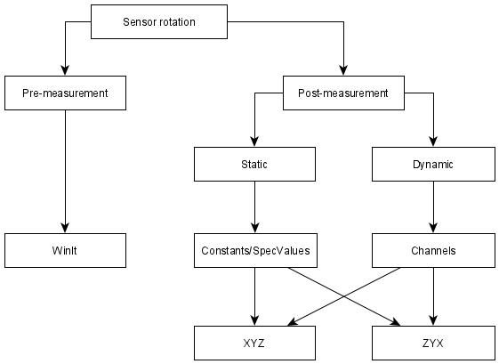
Rotational correction
Attention
Before any post-measurement rotation is executed, the output variables must be prepared with the function ChannelArray!
Rotation by Constants/SpecSheet values
Rot_3D_XYZ
Syntax |
|---|
C1=Rot_3D_XYZ(#SourceCH1, #SourceCH2, #SourceCH3, Angle1, Angle2, Angle3) |
Meaning |
Rotating the input Channels #SourceCH1 by value of Angle 1, #SourceCH2 by value of Angle2 and #SourceCH3 by value of Angle3 |
Rot_3D_ZYX
Important
This function is same as previous but using another rotational convention!
Rotation by channel values
Rot_3D_XYZ_Var
Syntax |
|---|
C1=Rot_3D_XYZ_Var(#SourceCH1, #SourceCH2, #SourceCH3, #RotateCH1, #RotateCH2, #RotateCH3) |
Meaning |
Rotating the input Channels #SourceCH1 by value of #RotateCH1, CH2 by value of #RotateCH2 and #SourceCH3 by value of #RotateCH3 |
Rot_3D_ZYX_Var
Important
This function is same as previous but using another rotational convention!
Example:
Rotating all three axes of an Accelerometer by SpeSheet-Values.
[RotateAcc]
Acc = ChannelArray('_x_1_R','_y_1_R','_z_1_R')
Acc = Rot_3D_XYZ(#Acc_x_1_F,#Acc_y_1_F,#Acc_z_1_F, Sensor_1.Rot_x, Sensor_1.Rot_y, Sensor_1.Rot_z)
Code explanation:
At first the output channels #Acc_x_1_R, #Acc_y_1_R and #Acc_z_1_R of the subsequent rotation are prepared.
Afterwards, the actual rotation takes place:
Channel #Acc_x_1_F is rotated by the SpecSheet value of group Sensor_1 entry Rot_x and the values are transferred to output channel #Acc_x_1_R
Channel #Acc_y_1_F is rotated by the SpecSheet value of group Sensor_1 entry Rot_y and the values are transferred to output channel #Acc_y_1_R
Channel #Acc_z_1_F is rotated by the SpecSheet value of group Sensor_1 entry Rot_z and the values are transferred to output channel #Acc_z_1_R
Madgwick_IMU_AHRS
The function Madgwick_IMU_AHRS uses the gyroscope and accelerometer channels of all respective axes to create quaternions, which is a four-dimensional complex number that can be used to represent the orientation of a rigid body or coordinate frame in three-dimensional space.
Madgwick filter fuses angular velocities, not solid angles. From the accelerometer data, a gradient method is used to calculate a vector with direction and magnitude of rotation. The same is calculated from the data of the gyroscope and then merged. Only after this calculation an integration after time takes place.
Inclusion of the accelerometer data takes place to compensate the gyroscope drift and magnetic interference.
Important
This function is able either to output quaternions (4 values) or Eulers angles (3 values). It is controlled by the number of the prepared output channels of ChannelArray!
Syntax |
|---|
C1=Madgwick_AHRS_IMU(#GYRO_x, #GYRO_y, #GYRO_z, #ACC_x_1, #ACC_y, #ACC_z, Value) |
Meaning |
Creating a four-dimensional complex number or either three Eulers angles to represent an orientation of a rigid body or coordinate frame in three-dimensional space. The parameter Value determines the inclusion of accelerometer data for gyro-drift compensation. |
Important
The amount of prepared output channels determines if output is in
Important
Value is 0.0 when no compensation should take place
Example 1:
Creating four quaternion-channels #Quat_q0, #Quat_q1, #Quat_q2 and #Quat_q3.
[Madgwick_Quaternionen]
Quat = ChannelArray('_q0', '_q1', '_q2' , '_q3')
Quat = Madgwick_AHRS_IMU(#Gyro_x, #Gyro_y, #Gyro_z, #Acc_x, #Acc_y, #Acc_z, 0.0)
Example 2:
Creating three Eulers angles #Quat_x, #Quat_y and #Quat_z.
[Madgwick_Euler]
Quat = ChannelArray('_x', '_y', '_z')
Quat = Madgwick_AHRS_IMU(#Gyro_x, #Gyro_y, #Gyro_z, #Acc_x, #Acc_y, #Acc_z, 0.0)
Filter function
Filters are used to smoothen a noisy signal or to obtain information about the dynamic movement of a signal (suspension, etc.). With the following functions, filtered channels can be calculated!
CalcTool provides two methods of defining a filter:
Simple filter interface
Only filter frequency must be defined by user. For all other values of the filter definition, default values are taken.
In most cases these values lead to the wanted result.
Full filter interface
For more individual or more advanced tasks, FIR-Filter (Finite Impulse Response-Filter) and IIR-Filters (Infinite Impulse Response-Filters) can be used!
Simple filter interface
This function is a predefined FIR (Finite Impulse Response) Low Pass filter with Hamming-window.
Important
Due to the FIR behaviour, only values preceding the current sample are included in the filtering.
The parameter Number of Iterations is determined as follows:
OR
Attention
Always the smaller value is taken! Thus, maximal NumberOfIterations is 401!
Attention
NumbersOfIterations must be odd!
Syntax |
Meaning |
|---|---|
C1=F(#CH, F(CrossFrequency)) |
Filtering #CH Hamming window and a determined CrossFrequency in Hz/Sec/s or Scans |
Example:
[FIR_LP_SimpleInterface]
Result = F(#V_Sat, F(2.0 Hz))
Assuming, the speed channel #V_Sat is sampled with 25 Hz and should be filtered with a CrossFrequency of 2.0 Hz using Hamming Window.
The calculated Number of Iterations therefore is:
Since the result is less than 401, the calculated value is used, but set to an odd value:
\(NumberOfIterations = 251\)
Full filter interface
Important
The full filter interface of CalcTool gives you also the possibility to define all parameters of a filter function
Syntax |
|---|
C1= F(#CH, F(FilterType WindowType CrossFrequency NumberOfIterations)) |
Important
There is only one space character between the filter parameters
Filter Type: |
|
|---|---|
L_P |
Low pass filter |
H_P |
High pass filter |
B_P |
Bandpass filter |
AVG |
Center average filter (Average built from NumberOfIterations of values, half left of current sample and the other half right of current sample) |
AVG+ |
Look ahead average filter (Average built from NumberOfIterations of values, only with samples right of current sample) |
AVG- |
Look back average filter (Average built from NumberOfIterations of values, only with samples left of current sample) |
MED |
Median filter |
TOP |
Maximum filter (like Median, but using the maximum value from the given interval) |
MAX |
|
BOT |
Minimum filter (like median, but using the minimum value from the given interval) |
MIN |
|
TAU |
Tau filter according to formula:
\[XFiltered(t)\ = \ XFiltered(t - 1)\ + \ 1/Iterations\ *\ (X(t)\ \ XFiltered(t - 1))\]
Iterations can be a floating-point number! If filter is used as in Magneti Marelli:
\[Iterations = \frac{1}{\text{filter\ value}}\]
|
Window Type: |
|
|---|---|
Rectangle |
|
Hann |
Hanning |
Hamm |
Hamming |
Blck |
Blackman |
Kaib |
Kaiser Bessel |
Parz |
Parzen |
Wlch |
Welch |
Cross frequency: |
|---|
Input of desired cross frequency |
Number of Iterations: |
|---|
Input of desired Number of Iterations |
Attention
If characters “Sec” or “s” are placed at position of NumberOfIterations, CalcTool calculates the iterations from given time value using the sampling rate of input channel!
Example 1:
Calculating an average of 100Hz-channel V_GPS 0.25 sec before and after current sample with a center average filter using a rectangular window.
Time-input in [sec]:
[Center_AVG_Filter_Time_SEC]
Result = F(#V_Sat, F(AVG 0.5 sec))
Time-input in [s]:
[Center_AVG_Filter_Time_S]
Result = F(#V_Sat, F(AVG 0.5 s))
Frequency-input in [Hz]
[Center_AVG_Filter_Time_SEC]
Result = F(#V_Sat, F(AVG 2 Hz))
Scan-input:
[Center_AVG_Filter_Time_Scans]
Result = F(#V_Sat, F(AVG 50))
–> The calculation results are the same!
Example 2:
The speed #V_GPS is filtered with a low pass filter with a Hanning window, a cross frequency of 2.0 Hz and the number of iterations is 100.
[LP_Hanning]
Result = F(#V_GPS, F(L_P Hann 2.0Hz 100))
Full filter interface with variable depth
In some cases, it might be useful not to use a fix depth for filtering but a variable. To address these cases, it is possible to define a filter with a variable filter depth.
Important
The depth of the filter is given by a channel
Attention
Only determine FilterTypes can be used with variable depth!
Syntax |
Meaning |
|---|---|
C1=F(#CH, F( FilterType #DepthChannel)) |
Filtering #CH with different FilterTypes with a variable depth depending on value of #DepthChannel |
*Filter Type:* |
|
|---|---|
AVG |
Centre average filter (Average built from NumberOfIterations of values, half left of current sample and the other half right of current sample) |
AVG+ |
Look ahead average filter (Average built from NumberOfIterations of values, only with samples right of current sample) |
AVG- |
Look back average filter (Average built from NumberOfIterations of values, only with samples left of current sample) |
MED |
Median filter |
TOP |
Maximum filter (like Median, but using the maximum value from the given interval) |
MAX |
|
BOT |
Minimum filter (like median, but using the minimum value from the given interval) |
MIN |
Example:
The example shows a centre average filter, where the depth of the filter is dependent on the temporary channel “C1”. This channel C1 is calculated to 1/250 of the RPM signal of the vehicle in the first line. The higher the RPM signal of the engine, the deeper is the filter.
[Center_AVG_Filter_Filter_VarDepth]
C1 =/(#RPM, 250)
Result = F(#Susp_F, F(AVG #C1))
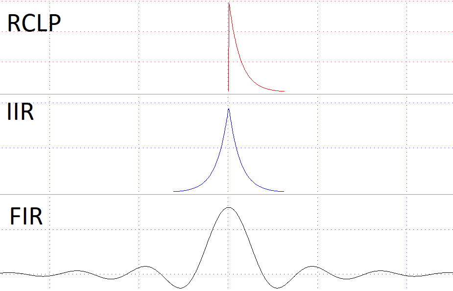
RCLP-Filter
The RCLP (resistor-capacitor lowpass) function behaves like an analogue 6dB RC lowpass filter.
Important
Due to the analogue filter attribute, this function can also be executed online in Logger during recording!
Syntax |
Meaning |
|---|---|
C1=RCLP(#CH, CrossFrequency HZ) |
Filtering #CH with an analogue RC lowpass filter with CrossFrequency in Hz/Sec/s |
IIR-Lowpass-Filter
The IIR is an extension of the RCLP filter to a 12dB recursive filter. In addition to the forward RCLP filter, this filter calculates an inverse, backward RCLP filter to obtain a time discretization.
Important
Especially for time crucial calculations it is recommended to use IIR filters!
Important
With IIR-Lowpass-Filter a Bandpass-Filter can be formed!
Syntax |
Meaning |
|---|---|
C1=F(#CH,F(IIR(CrossFrequency HZ))) |
Filtering #CH with IIR lowpass filter with CrossFrequency in Hz/Sec/s |
Comparison of impulse responses
Impulse response to a peak with amplitude 1 and duration of 1 ms.
Filter Comparison
Important
Due to the forward and backward filtering of the IIR filter the amplitude of the filtered channel is smaller than the amplitude of the channel filtered by the RCLP filter!
Frequency adjustments
New main frequency
This function allows you to change the main frequency of the measurement.
Sampled frequency can be reduced (information will be lost) as well as increased (not more information is created).
Syntax |
Meaning |
|---|---|
NewMainFreq(NewRate) |
Change samplingrate of the measurement to NewRate |
Attention
NewRate must be a multiple of the current rate!
Frequency reduction/increase
This function changes frequency of a channel with interpolation to changed frequency.
Sampled frequency can be reduced (information will be lost) as well as increased (not more information is created).
Syntax |
Meaning |
|---|---|
C1=Freq(#CH, NewRate) |
Change Samplingrate of Channel #CH with interpolation to NewRate |
Important
To reduce memory required for calculations, channel frequencies can be reduced!
Important
Values will be interpolated when changing frequency of channel!
Example:
See example Gear Interpolation in following chapter.
Frequency reduction/increase without interpolation
This function changes frequency of a channel without interpolation to changed frequency.
Sampled frequency can be reduced (information will be lost) as well as increased (not more information is created).
Syntax |
Meaning |
|---|---|
C1=FreqNI(#CH, NewRate) |
Change Samplingrate of Channel #CH with no Interpolation to NewRate |
Important
To reduce memory required for calculations, channel frequencies can be reduced!
Example:
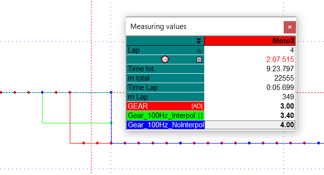
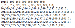
Interpolation
To save memory the frequency of #Gear is set from 500 Hz to 100 Hz with and without interpolation
#GEAR changes from 4 to 3. The interpolated channel #Gear_100Hz_Interpol obtains an intermediate value 3.40 by the interpolation during gear change while the next smaller gear is directly shown at #Gear_100Hz_NoInterpol.
#Gear_100Hz_Interpol and #Gear_100Hz_NoInterpol do not show the gear change at the same positions as #GEAR, so both lose information compared to #GEAR.
GPS commands
Sampling rate adjustment for non 2D sampling rates
If a 2D device is used to record data from CAN bus, it is possible that refresh rates of foreign GPS-CAN-devices does not match with one of the possible recording rates of the 2D-logger.
Example:
A foreign GPS device sends its data at 4 Hz.
The possible logger sampling rates are 400 Hz, 200 Hz, 100 Hz, 50 Hz, 25 Hz and 12.5 Hz.
50 Hz was selected to be the sampling rate for the loggers GPS channels.
In this case, the combination of 4 Hz refresh-rate and 50 Hz sampling rate, has the consequence, that one GPS-sample is each recorded 12.5 (50Hz/4Hz =12.5) times at the logger.
Since it is not possible to have a value a half time, the channel has 12 or 13 identical values for each GPS-sample. The different number of the same samples can result in aliasing.
This issue is solved by the command FreqBase which sets the number of identical values always to the same.
Syntax |
Meaning |
|---|---|
C1=FreqBase(#CH, NewRate, GPSRate) |
Adjusting the sampling rates of foreign GPS-devices channel #CH with a refresh rate GPSRate to 2D-logger sampling rates NewRate. |
#CH |
Name of the channel |
|---|---|
NewRate |
New samplingrate |
GPSRate |
Rate at which the GPS sends new data |
Attention
Value for NewRate must be less or equal to the main sampling rate of the logger!
Attention
NewRate must be divisible by the GPSRate without rest!
Continuation of example:
The GPS sends speed data (#V_SAT) with 4 Hz.
The data is recorded with a sampling rate of 50 Hz.
The NewRate must be a sampling rate of the logger and must be divisible by 4.
Thus, in this case the lowest possible NewRate is 100:
C1 = FreqBase(#V_Sat, 100, 4)
Find GPS frequency
This function is a special function for GPS recordings. Normally the GPS channels are recorded with a higher rate than the GPS antenna sends new values.
This function determines the real refresh rate of the GPS antenna based on the value changing of a channel.
Syntax |
Meaning |
|---|---|
C1= FindGPSFreq(#GPS_Channel) |
Finds the GPS frequency via the used GPS channel |
Important
#V_Sat or #SSHH are adequate channels to determine real refresh rate of GPS antenna
GPS shift
Important
Usable for all GPS modules which provide a channel named “T_Shift” additionally to normal GPS channels
Important
This channel indicates, how much milliseconds ago the values of the other channels were valid.
Syntax |
Meaning |
|---|---|
C1=GPSShift(#GPSChannel, #ShiftChannel, NewFreq) |
Create channel C1 with the frequency of NewRate and the data of #GPSChannel shifted by the time of #ShiftChannel |
GPSChannel |
Determine which channel will be outputted as #C1 with applied shift time |
|---|---|
ShiftChannel |
Additional GPS channel #T_Shift provided by GPS module in [Scans] |
NewFreq |
Sampling Rate of resulting channel #C1 |
Important
The higher the frequency is, the Shift function works more exactly (it must be always rounded on whole scans).
Important
NewFreq must be less or equal main sampling rate! If bigger, a warning appears that main sampling rate is used!
Important
Result channels are always channels of type float (double if the GPS channel was double, otherwise channels with a single precision)
Important
Between the “shifted” GPS values a linear interpolation will be done.
Make32GPS
Syntax |
Meaning |
|---|---|
C1=Make32GPS(#CH) |
Change data type from 32-bit, integer GPS-channel to double precision with output range of -180°…+180° |
Important
Input channel #CH must be a 32-bit-channel (normally #Latitude or #Longitude)
Important
The resulting channel #C1 will be a double precision channel with range -180° … +180°
Channel manipulation
Demultiplexing a multiplexed channel
To reduce the traffic on the CAN bus, sometimes more than one channel is sent on a single identifier at the same byte position. In order to interpret the data on the data channel the interpretation information must be sent to my other channel.
Syntax |
Meaning |
|---|---|
C1=MUX(#DataChannel, #MuxChannel, MuxVal) |
Channel MuxVal specifies with which multiplex information #MuxChannel the multiplex data on #DataChannel should be read |
#DataChannel |
Name of the channel containing the multiplexed data |
|---|---|
#MuxChannel |
Name of the channel containing the multiplex information (0/1) |
MuxVal |
Decision value which data of #DataChannel should be read |
Example:
[OilTemp]
Result = MUX(#Fluid_Temp, #Fluid_Temp_MUX, 1)
The channel “Fluid_Temp” contains multiplexed data for water- and oil-temperature
In this case #Fluid_Temp_MUX=0 stands for water temperature and #Fluid_Temp_MUX=1 stands for oil temperature.
Due to the MuxVal=1 the resulting channel #Oil_Temp will have the oil temperature values.
Masking out used bits
To use as few identifiers as possible it is usual to aggregate more than one channel in a 8, 16 or 32 bit value on the CAN bus. With 2D devices it is only possible to record up to four whole bytes from the CAN-bus.
Sometimes it is necessary to mask out only several bits from the recorded channel, this can be done by using the UseBits function.
Syntax |
Meaning |
|---|---|
C1=UseBits(#DataChannel, MaskValue) |
Extracts the values of #DataChannel using #MaskValue to mask out bits. |
Example:
The channel “DataChannel” is a 16-bit channel recorded from the CAN bus.
The four least significant bits represent the selected gear of the vehicle.
The 12 most significant bits represent the speed.
[Gear]
Result = UseBits(#DataChannel, 0b1111)
[Speed]
Result = UseBits(#DataChannel, 0b1111111111110000)
Written in hexadecimal notation:
[Gear]
Result = UseBits(#DataChannel, 0hF)
[Speed]
Result = UseBits(#DataChannel, 0hFFF0)
Important
Different notations are possible!
Shifting a channel
This function allows to shift a channel on the time axis. The unit for the shift may either be seconds or scans.
Syntax |
Meaning |
|---|---|
C1=Shift(#CH, Constant) |
Shifting #CH by the number of scans |
C1=Shift(#CH, Constant sec) |
Shifting #CH by time in seconds |
Important
One scan is the time between two measured values of the channel. That means if the channel is recorded with 50 Hz one scan is 1/(50 Hz) ⇔ 0.02 sec.
Important
Negative number of scans or time Shifting to left
Important
Positive number of scans or time Shifting to right
Examples:
[V_Front_Shift_BySamples_ToLeft]
Result = Shift(#V_Front, -200)
[V_Front_Shift_ByTime_ToLeft]
Result = Shift(#V_Front, - 0.05 sec)
Important
In both cases, #VFront was shifted the same, because of the formula \(f = \frac{1}{t}\)
Combining 16-bit channels
Most 2D modules have the possibility to record CAN channels with 16-bit resolution as well as 32-bit resolution. If the logger does not provide enough 32-bit channels to record data, the information can be split in two 16-bit channels.
After downloading the data, these two 16-bit channels can be combined to one 32-bit channel using the following functions:
*Name* |
Meaning |
*Output-Range* |
|---|---|---|
Make32 |
Combine two 16-bit channels to one integer 32-bit channel |
0°…360° |
MakeGPS |
Combine two 16-bit channels to one integer 32-bit channel |
-180°…+180° |
MakeSingle |
Combine two 16-bit channels to one single-precision 32-bit channel |
Make32
Syntax |
Meaning |
|---|---|
C1=Make32(#CHHi, #CHLo) |
Combine two 16-bit channels to one integer 32-bit channel |
#CHHi |
Input channel containing the high 16 bits |
|---|---|
#CHLo |
Input channel containing the low 16 bits |
Important
Output-Range: 0°…360°
Important
The resulting channel C1 receives the calibration formula of #CHLo
Example:
Combining two 16-bit channels to global Latitude with range 0°…360°
[Latitude]
Result = MAKE32(#LatituHi, #LatituLi)
MakeGPS
Syntax |
Meaning |
|---|---|
C1=MakeGPS(#CHHi, #CHLo) |
Combine two 16-bit channels to one integer 32-bit channel |
#CHHi |
Input channel containing the high 16 bits |
|---|---|
#CHLo |
Input channel containing the low 16 bits |
Important
Output-Range: -180°…+180°
Important
The resulting channel C1 receives the calibration formula of #CHLo
Example:
Combining two 16-bit channels to global Latitude with range -180°…+180°
[Latitude]
Result = MAKEGPS(#Lat_deHi, #Lat_deLo)
MakeSingle
Syntax |
Meaning |
|---|---|
C1=MakeSingle(#CHHi, #CHLo) |
Combine two 16-bit channels to one single-precision 32-bit channel |
#CHHi |
Input channel containing the high 16 bits |
|---|---|
#CHLo |
Input channel containing the low 16 bits |
Important
The resulting channel C1 receives the calibration formula of #CHLo
Combining 32-bit channels
If channels are recorded from the CAN bus (see chapter before), it might be possible, that the data sent by a CAN device has a resolution of 64 bit. As there are not many modules able to record 64-bit channels, the information might be split in two 32-bit channels or four 16-bit channels.
Therefore, a 64-bit channel must be created.
The following functions can be used:
*Name* |
Meaning |
|---|---|
Make64 |
Combine two 32-bit channels to one integer 64-bit channel |
MakeDouble |
Combine two 32-bit channels to one single-precision 64-bit channel |
If only 16-bit channels are provided, this must be done in two steps:
Combining four 16-bit to two 32-bit channels using the Make32 function
Combining these two 23-bit channels to one 64-bit channel.
Make64
Syntax |
Meaning |
|---|---|
C1=MAKE64(#CHHi, #CHLo) |
Combine two 32-bit channels to one integer 64-bit channel |
#CHHi |
Input channel containing the high 32 bits |
|---|---|
#CHLo |
Input channel containing the low 32 bits |
Important
The resulting channel C1 receives the calibration formula of #CHLo
MakeDouble
Syntax |
Meaning |
|---|---|
C1=MakeDouble(#CHHi, #CHLo) |
Combine two 32-bit channels to one single-precision 64-bit channel |
#CHHi |
Input channel containing the high 32 bits |
|---|---|
#CHLo |
Input channel containing the low 32 bits |
Important
The resulting channel C1 receives the calibration formula of #CHLo
Example:
Combining four 16-bit channels to a double-precision, 64-bit channel
[Double]
c1 = Make32(#LoHi, #LoLo)
c2 = Make32(#HiHi, #HiLo)
Result = MakeDouble(#c1, #c2)
If Function
This function is used to compare one channel with a constant or another channel.
Depending on whether the condition was fulfilled, the resulting receives either the value of TrueResult or FalseResult.
Syntax |
Meaning |
|---|---|
C1=if(#CH, Operator, #CH , TrueResult, FalseResult) |
Comparing two channels |
C1=if(#CH, Operator, Constant , TrueResult, FalseResult) |
Comparing channel with constant |
*Possible Operators:* |
|
|---|---|
> |
Bigger than |
< |
Smaller than |
>= |
Same and bigger than |
<= |
Same and smaller than |
<> |
Bigger and smaller than |
= |
Same |
Example:
c1 = if(#V_Sat, >, 10, 1, 0)
Important
Depending on whether the condition was fulfilled, channel C1 receives either the value of TrueResult or FalseResult
Important
TrueResult & FalseResult can also be constants
Important
If function is often used to get a True/False evaluation
SOD
To provide a more convenient use of the time of day, the time is converted into seconds. This is done with the command SOD (SecondsOfDay).
Syntax |
Meaning |
|---|---|
C1=SOD(#HHMM, #SSHH) |
Calculating Seconds of Day from channels #HHMM and #SSHH |
C1=SOD(#HHMM, #SSHH, Rate) |
Calculating Seconds of Day from channels #HHMM and #SSHH and set output rate of created channel |
Example:
Time |
13:40:45.258 |
|---|---|
#HHMM |
13.40 |
#SSHH |
45.258 |
HH |
13 h |
*3600 |
46800.000 sec |
|---|---|---|---|
MM |
40 min |
*60 |
2400.000 sec |
SS |
45 sec |
*1 |
45.000 sec |
HH |
0.258 sec |
*1 |
0.258 sec |
SecondsOfDay |
49245.258 sec |
||
Mathematical functions
Addition
CalcTool supports following types of additions:
Syntax |
Meaning |
|---|---|
C1=+(#CH1, #CH2) |
Addition of channels |
C1=+(#CH, Constant) |
Addition of channel and constant |
Important
Multiplication in connection with if-function can also be used for Logic-OR-function
Subtraction
CalcTool supports following types of subtractions:
Syntax |
Meaning |
|---|---|
C1=-(#CH1, #CH2) |
Subtraction of channel |
C1=-(#CH, Constant) |
Subtraction of channel and constant |
Multiplication
CalcTool supports following types of multiplications:
Syntax |
Meaning |
|---|---|
C1=*(#CH1, #CH2) |
Multiplication of channels |
C1=*(#CH, Constant) |
Multiplication of channel and constant |
Example:
Squaring a channel.
[Speed_Square]
Result = *(#Speed, #Speed)
Important
Multiplication in connection with if-function can also be used for Logic-AND-function
Division
CalcTool supports following types of divisions:
Syntax |
Meaning |
|---|---|
C1=/(#CH1, #CH2) |
Division of channels |
C1=/(#CH, Constant) |
Division of channel and constant |
Example1:
Conversion of speed from [km/h] to [m/s]
[Speed_MS]
Result = /(#Speed_kmh, 3.6)
Example2:
Conversion of speed from [km/h] to [mph]
[Speed_mph]
Result = *(#Speed_kmh, 1.62)
Modulo
The result of the modulo function is the rest of a division:
CalcTool support following kinds of modulo functions:
Syntax |
Meaning |
|---|---|
C1=Mod(#CH1, #CH2) |
Modulo of channels |
C1=Mod(#CH, constant) |
Modulo of channel and constant |
Example:
Masking out lowest 5 bits Lo5Bit=Mod(#CH, 32)
Important
Can be used for masking out bits
Important
Can be used for incremental counters
Integer division
The result of the DIV function (integer division) is the quotient of an integer division without rest
CalcTool supports following kinds of DIV functions:
Syntax |
Meaning |
|---|---|
C1=Div(#CH1, #CH2) |
Integer Division of channels |
C1=Div(#CH, Constant) |
Integer Division of channel and constant |
Logarithm
This function allows you to calculate the decimal logarithms from any channel.
Syntax |
Meaning |
|---|---|
C1=Log(#CH) |
Calculating the decimal logarithm of #CH |
Absolute value
This function gives the absolute value of the calculated channel.
Syntax |
Meaning |
|---|---|
C1=Abs(#CH) |
Calculating the absolute value of #CH |
Minimum
The channel which currently has the lower value is the resulting channel.
Syntax |
Meaning |
|---|---|
C1=Min(#CH1, #CH2) |
Result of this function is the minimum of the two compared channels |
Example:
Comparing car left and right rear suspension and always take the minimum of these two channels.
Maximum
The channel which currently has the higher value is the resulting channel.
Syntax |
Meaning |
|---|---|
C1=Max(#CH1, #CH2) |
Result of this function is the maximum of the two compared channels |
Example:
Comparing car left and right rear suspension and always take the maximum of these two channels.
Derivation
Formation of the mathematical derivation of a channel.
There are two different possibilities to execute a derivation:
Syntax |
Meaning |
|---|---|
C1=Derivate(#CH) |
Executing a mathematical derivation of #CH |
C1=F’(#CH) |
Important
The names of derivation-commands differ, but the functionality of both is the same.
Example 1:
Deriving the speed of the vehicle to get longitudinal acceleration [km/h] [m/s²]
Attention
If a channel with dimension [km/h] is derived, the conversion from [km/h] to [m/s] is done automatically and the resulting channel gets the dimension [m/s²]
Example 2:
Deriving travel of the fork to get the speed of fork movement [mm] [mm/s]
*Example3:*
Deriving a channel to get local turn-around points.
Integration
Formation of the mathematical integration of a channel
Syntax |
Meaning |
|---|---|
C1=Integrate(#CH) |
Executing a mathematical integration of #CH |
C1=Integrate(#CH , Value) |
Executing a mathematical integration of #CH, set resulting channel #C1 at every laptrigger to Value |
Important
Value 0 must be used to calculate the resulting value per lap
Example 1:
Calculate energy from the physical values of a channel (e.g. on brake signal to know energy spent by lap).
Example 2:
Integrate speed of longitudinal acceleration of vehicle to get speed [m/s²] [m/s]
Attention
If a velocity is first derived to an acceleration by means of derivation and this acceleration is then integrated so that a velocity is obtained again, the velocity resulting from integration will have a small difference to the original velocity which is due to the integration constant!
Sum
This function calculates the sum of all values of a channel.
Syntax |
Meaning |
|---|---|
C1=Sum(#CH) |
Calculating the sum of all values of a channel |
C1=Sum(#CH , Value) |
Calculating the sum of all values of a channel, set resulting channel #C1 at every laptrigger to Value |
Important
Value 0 must be used to calculate the resulting value per lap
Example 1:
Counting up or down-shifts per lap.
Power
Executing exponential calculations.
Syntax |
Meaning |
|---|---|
C1=Power (#CH1, #CH2) |
Base as channel & Exponent as channel |
C1=Power (#CH, Constant) |
Base as channel & Exponent as constant |
C1=Power (Constant, #CH) |
Base as constant & Exponent as channel |
Eulers exponent
Executing exponential calculations with base Euler’s constant.
Syntax |
Meaning |
|---|---|
C1=Exp(#CH) |
Executing exponential calculations with base Euler’s constant. |
Important
Also possible: C1=Power(@E, #CH)
Square root
Calculating the square root of a channel.
Attention
Calculation is made with the absolute value of channel!
Syntax |
Meaning |
|---|---|
C1=SQRT(#CH) |
Calculating the square root of a channel. |
Example:
Calculation of combined Gs for a car to define the total tractive effort available for braking while turning.
\(Combined\_ Gs = \sqrt{\left( \text{Latera}l_{\text{Gs}} \right)^{2} + (Longitudunal_{\text{Gs}})}\)
Signum
Evaluating sign of channel value
Syntax |
Meaning |
|---|---|
C1=Sig(#CH) |
Creating a channel value (-1, 0 or +1), depending on the channels value sign |
Example:
> 0 |
–> |
+1 |
< 0 |
–> |
-1 |
= 0 |
–> |
0 |
Rounding values
CalcTool provides three different functions to round fractional numbers to integers.
Round
Rounding a channel value to an integer.
Syntax |
Meaning |
|---|---|
C1=Round (#CH) |
Rounding channel to an integer |
Important
The rounding function set the result to the next higher integer if the fraction of the channel value is greater than or equal to 0.5
Important
If the fraction is smaller than 0.5 it goes to the next smaller integer value
Example:
1.5 |
–> |
2 |
-1.5 |
–> |
-1 |
1.49 |
–> |
1 |
Floor
Rounding a channel value to next smaller integer.
Syntax |
Meaning |
|---|---|
C1= Floor (#CH) |
Rounding channel to next smaller integer |
Example:
1.5 |
–> |
1 |
-1.5 |
–> |
-2 |
1.99 |
–> |
1 |
Trunc
Cutting the fractional part of a channel value.
Syntax |
Meaning |
|---|---|
C1=Trunc(#CH) |
Cutting the fractional part of a channel value |
Example:
1.5 |
–> |
1 |
-1.5 |
–> |
-1 |
1.00 |
–> |
1 |
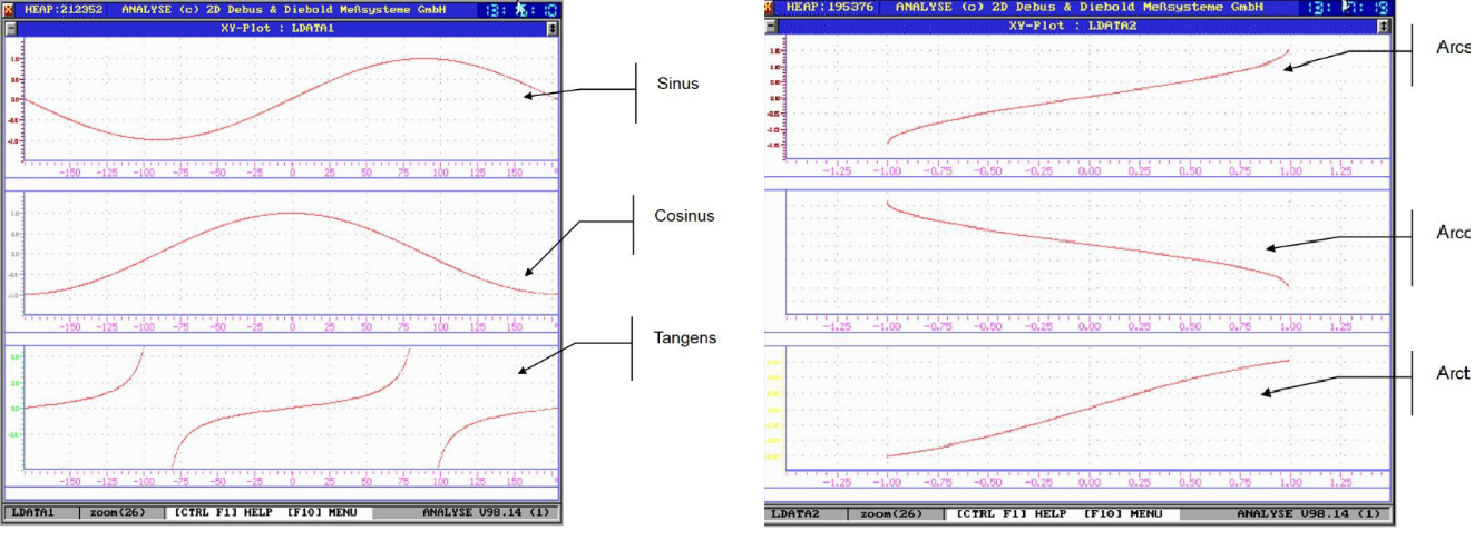
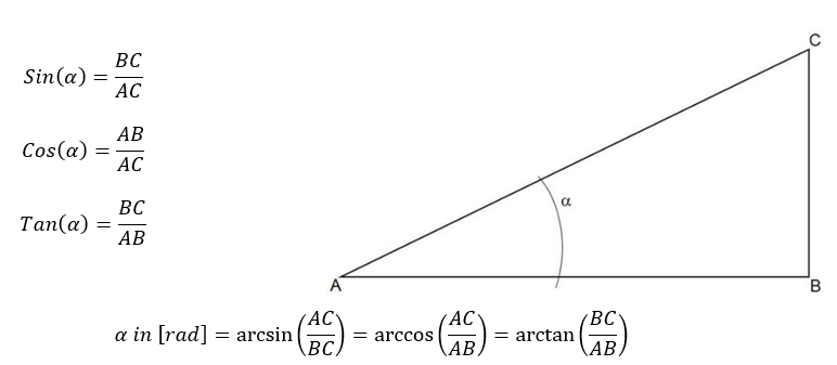
Trigonometric functions
These functions allow you to calculate the sine, cosine, tangent, arcsine, arccosine and arctangent of a channel.
Important
The input for sine, cosine and tangent functions can be in radians or degrees
Important
The result for arcsine, arccosine and arctangent will be only in radians.
Syntax |
Meaning |
Comment |
|---|---|---|
C1=dsin(#CH) |
Sine(#CH) |
(Resulting channel in degrees) |
C1=dcos(#CH) |
Cosine(#CH) |
(Resulting channel in degrees) |
C1=dtan(#CH) |
Tangent(#CH) |
(Resulting channel in degrees) |
C1=sin(#CH) |
Sine(#CH) |
(Resulting channel in radians) |
C1=cos(#CH) |
Cosine(#CH) |
(Resulting channel in radians) |
C1=tan(#CH) |
Tangent(#CH) |
(Resulting channel in radians) |
C1=arcsin(#CH) |
Arcsine(#CH) |
(Resulting channel in radians) |
C1=arccos(#CH) |
Arccosine(#CH) |
(Resulting channel in radians) |
C1=arctan(#CH) |
Arctangent(#CH) |
(Resulting channel in radians) |
C1=arctan2(#CH1, #CH2) |
Arctangent2(#CH1, #CH2) |
(Resulting channel in radians) |
Important
Arctan2 extends the output of arctan-function from two to four quadrants!
Important
For conversion from degrees in radians and the other way round, pre-defined constants (see Constants) can be used.
Logical functions
Logical functions are binary, logical calculations.
Attention
These functions only work with WORD channels!
AND
CalcTool supports following types of AND functions:
Syntax |
Meaning |
|---|---|
C1=AND(#CH1,#CH2) |
Logical AND between channels |
C1=AND(#CH, Constant) |
Logical AND between channel and constant |
Example:
Mask out the lowest 8 bit of a channel (Lo8Bit=And(#CH, 0xFF)).
NAND
CalcTool supports following types of NAND functions:
Syntax |
Meaning |
|---|---|
C1=NAND(#CH1,#CH2) |
Logical NAND between channels |
C1=NAND(#CH, Constant) |
Logical NAND between channel and constant |
OR
CalcTool supports following types of OR functions:
Syntax |
Meaning |
|---|---|
C1=Or(#CH1, #CH2) |
Logical OR between channels |
C1=Or(#CH, Constant) |
Logical OR between channel and constant |
XOR
CalcTool supports following types of XOR functions:
Syntax |
Meaning |
|---|---|
C1=Xor(#CH1, #CH2) |
Logical XOR between channels |
C1=Xor(#CH, Constant) |
Logical XOR between channel and constant |
Not
CalcTool supports following types of NOT function:
Syntax |
Meaning |
|---|---|
C1=Not(#CH) |
Logical negation of the channel |
Signal analysis
VCount
Syntax |
Meaning |
|---|---|
C1= VCount(#CH) |
Increments a counter if channel value and its successive scan are equal |
Important
If the successive values are not equal, counter is reset to 0
CountValue
The function CountValue sums up all values of samples as long as #CH is inside the tolerance around value.
Syntax |
Meaning |
|---|---|
C1=CountValue(#CH, value, tolerance) |
Summing up all sample values as long as #CH is inside the tolerance around value |
Example:
Evaluating the sum of sample values when #T_Oil was between 90° +/-10°.
[SumOilTempValuesInRange]
Result = CountValue(#T_Oil, 90, 10)
DecWhileTrue
Decrements the first value of SourceChannel by 1 as long BoolChannel is > 0.
Syntax |
Meaning |
|---|---|
C1=DecWhileTrue(#SourceChannel, #BoolChannel) |
Decrements the first value of SourceChannel by 1 as long BoolChannel is > 0. |
Important
If #CheckChannel is = 0, #C1 is reset to 0
Important
Frequency of the resulting channel C1 corresponds to the fastest frequency of #SourceChannel
Minima
MinValue
The MinValue function searches all values of a given channel to find the minimum. It creates a channel with the constant value of this minimum.
Syntax |
Meaning |
|---|---|
C1=MinValue(#CH, Rate) |
Creates a channel #C1 with a constant corresponding to minimum value of #CH. Rate defines the sampling rate at which channel #C1 is saved. |
Important
If no Rate is defined, the resulting channel #C1 gets @MainSamplingrate as frequency
MinHoldWhileTrue
This function determines the minimum value of a SourceChannel as long as BoolChannel is > 0.
Important
The minimum value of the SourceChannel in the BoolChannel area is determined successively as long as the BoolChannel is > 0.
Syntax |
Meaning |
|---|---|
C1=MinHoldWhileTrue(#SourceChannel, #BoolChannel) |
Successive determination of minimum value of SourceChannel as long as BoolChannel is > 0. |
Important
If BoolChannel = 0 the resulting channel C1 carries the value of SourceChannel
Important
Frequency of the resulting channel C1 corresponds to the fastest frequency of #SourceChannel
MinWhileTrue
This function determines the minimum value of a SourceChannel as long as BoolChannel is > 0.
Important
The minimum value of the SourceChannel in the BoolChannel-Area is held as long as the BoolChannel is > 0.
Syntax |
Meaning |
|---|---|
C1=MinWhileTrue(#SourceChannel, #BoolChannel) |
Holding the minimum value of SourceChannel as long as BoolChannel is > 0. |
Important
If BoolChannel = 0 the resulting channel C1 carries the value of SourceChannel
Important
Frequency of the resulting channel C1 corresponds to the fastest frequency of #SourceChannel
PosMinWhileTrue
This function highlights the minimum value of a SourceChannel as long as BoolChannel is > 0 with a Boolean TRUE.
Important
The minimum value of the SourceChannel in the BoolChannel-Area is highlighted with a Boolean TRUE.
Syntax |
Meaning |
|---|---|
C1=PosMinWhileTrue(#SourceChannel, #BoolChannel) |
Highlighting the minimum value of SourceChannel as long as BoolChannel is > 0. |
Important
Frequency of the resulting channel C1 corresponds to the fastest frequency of #SourceChannel
EnvMin
The EnvMin function searches a certain number of values of a certain channel to find the minimum within this range.
Syntax |
Meaning |
|---|---|
C1=EnvMin(#CH, samples number) |
The EnvMin function searches a certain number of values of a certain channel to find the minimum within this range. |
Different minima functions
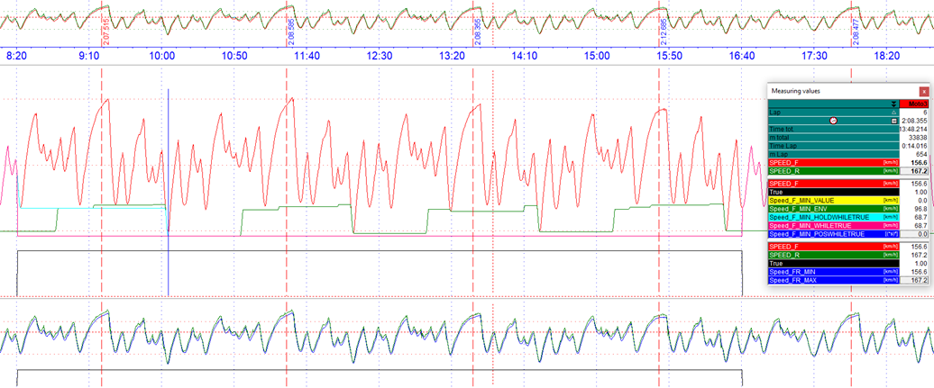
Different Minima functions
[MIN]
Speed_F_Min_Value         = MinValue(#Speed_F)
Speed_F_Min_ENV           = EnvMin(#Speed_F,5000)
Speed_FR_Min              = Min(#Speed_F, #Speed_R)
Speed_F_Min_HoldWhileTrue = MinHoldWhileTrue(#Speed_F, #True)
Speed_F_Min_WhileTrue     = MinWhileTrue(#Speed_F, #True)
Speed_F_Min_PosWhileTrue  = MinPosWhileTrue(#Speed_F, #True)
Maxima
MaxValue
The MaxValue function searches all values of a given channel to find the maximum. It creates a channel with the constant value of this maximum.
Syntax |
Meaning |
|---|---|
C1=MaxValue(#CH, Rate) |
Creates a channel #C1 with a constant corresponding to maximum value of #CH. Rate defines the sampling rate at which channel #C1 is saved. |
Important
If no Rate is defined, the resulting channel #C1 gets @MainSamplingrate as frequency
MaxHoldwhiletrue
This function determines the maximum value of a SourceChannel as long as BoolChannel is > 0.
Important
The maximum value of the SourceChannel in the BoolChannel area is determined successively as long as the BoolChannel is > 0.
Syntax |
Meaning |
|---|---|
C1=MaxHoldWhileTrue(#SourceChannel, #BoolChannel) |
Successive determination of maximum value of SourceChannel as long as BoolChannel is > 0. |
Important
If BoolChannel = 0 the resulting channel C1 carries the value of SourceChannel
Important
Frequency of the resulting channel C1 corresponds to the fastest frequency of #SourceChannel
MaxWhileTrue
This function determines the maximum value of a SourceChannel as long as BoolChannel is > 0.
Important
The maximum value of the SourceChannel in the BoolChannel-Area is held as long as the BoolChannel is > 0.
Syntax |
Meaning |
|---|---|
C1=MaxWhileTrue(#SourceChannel, #BoolChannel) |
Holding the maximum value of SourceChannel as long as BoolChannel is > 0. |
Important
If BoolChannel = 0 the resulting channel C1 carries the value of SourceChannel
Important
Frequency of the resulting channel C1 corresponds to the fastest frequency of #SourceChannel
PosMaxWhileTrue
This function highlights the maximum value of a SourceChannel as long as BoolChannel is > 0 with a Boolean TRUE.
Important
The maximum value of the SourceChannel in the BoolChannel-Area is highlighted with a Boolean TRUE.
Syntax |
Meaning |
|---|---|
C1=PosMaxWhileTrue(#SourceChannel, #BoolChannel) |
Highlighting the maximum value of SourceChannel as long as BoolChannel is > 0. |
Important
Frequency of the resulting channel C1 corresponds to the fastest frequency of #SourceChannel
EnvMax
The EnvMax function searches a certain number of values of a certain channel to find the maximum within this range.
Syntax |
Meaning |
|---|---|
C1=EnvMax(#CH, samples number) |
The EnvMax function searches a certain number of values of a certain channel to find the maximum within this range. |
Different maxima functions
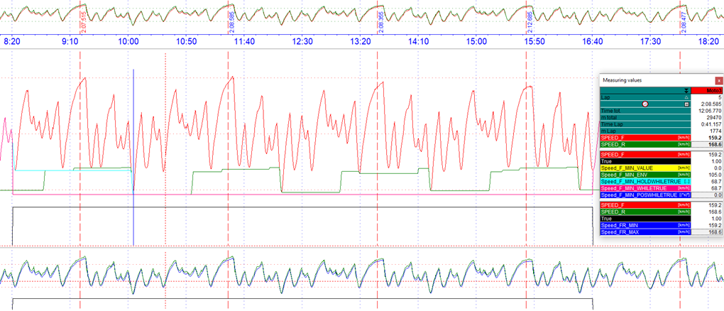
Different Maxima functions
[Max]
Speed_F_Max_Value         = MaxValue(#Speed_F)
Speed_F_Max_ENV           = EnvMax(#Speed_F,5000)
Speed_FR_Max              = Max(#Speed_F, #Speed_R)
Speed_F_Max_HoldWhileTrue = MaxHoldWhileTrue(#Speed_F, #True)
Speed_F_Max_WhileTrue     = MaxWhileTrue(#Speed_F, #True)
Speed_F_Max_PosWhileTrue  = MaxPosWhileTrue(#Speed_F, #True)
PeakPreView
The PeakPreView function determines a local maximum in an area defined by FallbackTreshholdNumber and holds the value of the local maxima and transfers it back to the previous local maxima.
Important
Before a new local maximum is found, the value of #CH must fall below the FallbackTreshold
Syntax |
Meaning |
|---|---|
C1=PeakPreview(#CH, FallbackThresholdNumber) |
Determine a local maximum of #CH in an area defined by FallbackTresholdNumber and transfers value of local maxima back to previous one. |
Important
FallbackTresholdNumber must be between 0 and 1
Example:
[PeakPreview]
Result    = PeakPreView(#Speed_F, 0.5)
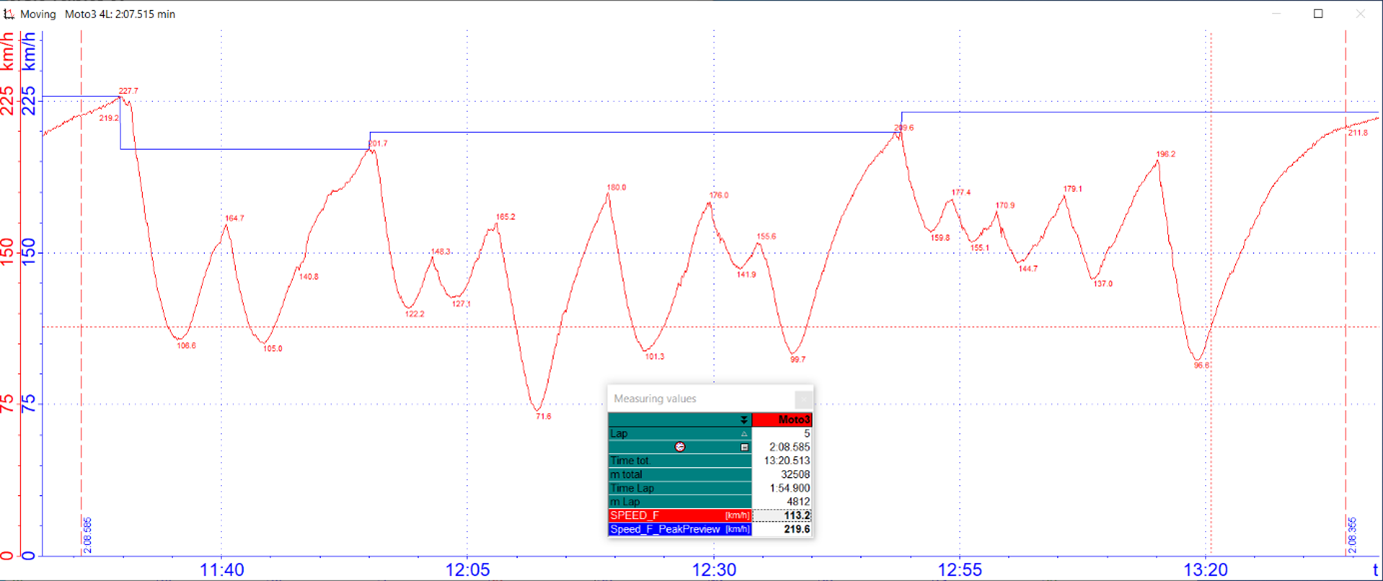
Peak Preview
First value
The FirstValue function reads the first value of a given channel and creates a constant channel using this value.
Syntax |
Meaning |
|---|---|
C1=FirstValue(#CH, Rate) |
Creates a channel #C1 with a constant corresponding to first value of #CH. Rate defines the sampling rate at which channel #C1 is saved. |
Last value
The LastValue function reads the last value of a given channel and creates a constant channel using this value.
Syntax |
Meaning |
|---|---|
C1=LastValue(#CH, Rate) |
Creates a channel #C1 with a constant corresponding to last value of #CH. Rate defines the sampling rate at which channel #C1 is saved. |
AvgValue
The AvgValue function calculates the average value of a given channel and creates a constant channel using this value.
Syntax |
Meaning |
|---|---|
C1= AvgValue(#CH, Rate) |
Creates a channel #C1 with a constant corresponding to average value of #CH. Rate defines the sampling rate at which channel #C1 is saved. |
AverageWhileTrue
AvgWhileTrue function continuously calculates the average value of a SourceChannel if a BoolChannel is > 0.
Syntax |
Meaning |
|---|---|
C1=AvgWhileTrue(#SourceChannel, #BoolChannel) |
Continuous calculation of average value of a SourceChannel if a BoolChannel is > 0. |
Important
If BoolChannel is = 0, resulting channel C1 is also 0
Important
Frequency of the resulting channel C1 corresponds to the fastest frequency of #SourceChannel
Limit
This function uses only the channel value between the limits. Minimum and maximum limit can be fix parameters or channel values.
Important
If the value of the checked channel is below the minimum limit, this value will be used, if it is greater than the maximum limit, that value will be used.
Syntax |
Meaning |
|---|---|
C1=Limit(#CH, minLimit, maxLimit) |
The value of the #CH will be used if its value is between the limits. Otherwise the value of the minimum or maximum limits will be used. |
Important
The limits can be constants or channels.
Rising Edge
The RisingEdge function is used for boolean detection of rising edges.
Important
If subsequent value of a channel is greater than the current value, then the function´s value is 1, otherwise 0.
Syntax |
Meaning |
|---|---|
C1=RisingEdge(#CH) |
#CH is checked on rising edges |
Falling Edge
The FallingEdge function is used for boolean detection of falling edges.
Important
If subsequent value of a channel is smaller than the current value, then the function´s value is 1, otherwise 0
Important
If falling edge is used for subsequent functions like FillFromBool please check position of Boolean detection and use Shift-function if necessary!
Syntax |
Meaning |
|---|---|
C1=FallingEdge(#CH) |
#CH is checked on falling edges |
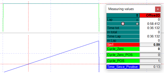
Zero Cross
The function ZeroCross is used to mark zero crossings of a signal boolean.
Syntax |
Meaning |
|---|---|
C1=ZeroCross(#CH) |
#CH is checked on zero crossings |
Important
With a zero crossing from the positive to the negative range the result of the ZeroCross-function = 1
Important
With a zero crossing from the negative to the positive range the result of the ZeroCross-function = -1
Example:
Marking zero crossing of a sinusoidal function.
[Cycle_Zero]
Result    = ZeroCorss(#Sin1)
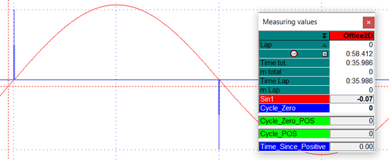
Zero Cross function
FillFromBool
With this function the value of a SourceChannel will be continued from the moment the BoolChannel was last > 0.
Syntax |
Meaning |
|---|---|
C1=FillFromBool(#SourceChannel, #BoolChannel) |
Take value from SourceChannel when BoolChannel is > 0 |
Important
Frequency of the resulting channel C1 corresponds to the frequency of BoolChannel.
Important
If BoolChannel is never > 0 inside the respective measurement, the resulting channel C1 permanently carries the first value of SourceChannel.
Example:
Analysis of local maxima
[LocalMax]
c1     = F'(#Sin)                   ; Derivation of #Sin
c1     = ZeroCross(#c1)             ; Find Zero Crossings of Derivation
c1     = if(#C1, =, 1, 0, #c1)      ; Only Maxima
Result = FillFromBool(#Sin, #c1)    ; Get last local Maxima
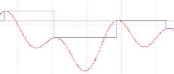
Analysis of local maxima
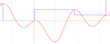
FillWithNextBool
With this function the value of a source channel will be continued from the moment the Boolean channel was next > 0.
Syntax |
Meaning |
|---|---|
C1=FillWithNextBool(#SourceChannel, #BoolChannel) |
Take value from SourceChannel when BoolChannel was last > 0 |
Important
Frequency of the resulting channel C1 corresponds to the frequency of BoolChannel.
Important
If BoolChannel is never > 0 inside the respective measurement, the resulting channel C1 permanently carries the value 0.
Example:
Analysis of local maxima
[LocalMax]
c1     = F'(#Sin)                   ; Derivation of #Sin
c1     = ZeroCross(#c1)             ; Find Zero Crossings of Derivation
c1     = if(#C1, =, 1, 0, #c1)      ; Only Maxima
Result = FillWithNextBool(#Sin, #c1); Get next local Maxima
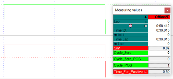
TimeForTrue
The TimeForTrue function displays the absolute time in seconds if the value of the channel is not zero. When the channel´s value goes back to zero, the value of this calculated channel is zero as well.
Syntax |
Meaning |
|---|---|
C1=TimeforTrue(#CH) |
As long as the value of the channel is bigger or smaller than 0, the absolute time the channel is not zero is displayed in seconds |
Example:
TimeForTrue of #CyclePos
[Time_For_Positive]
Result = TimeForTrue(#Cycle_Pos)
TimeSinceTrue
The TimeSinceTrue function counts the seconds if the channel value of a channel is not zero. When the channel´s value goes back to zero, the value of this resulting channel is zero as well.
Syntax |
Meaning |
|---|---|
C1=TimeSinceTrue(#CHl) |
As long as the value of the channel is bigger or smaller than 0, this time will be counted in seconds |
Example:
TimeSinceTrue of #CyclePos
[Time_Since_Positive]
Result = TimesinceTrue(#Cycle_Pos)
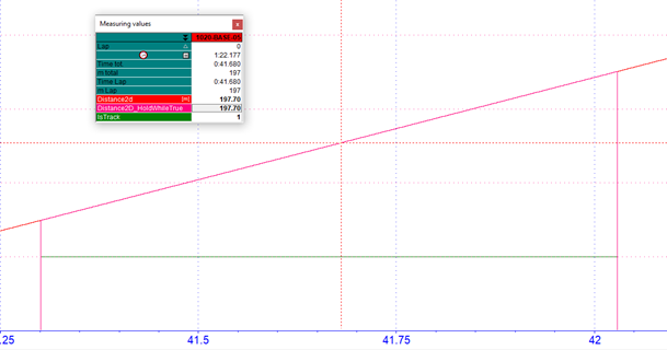
HoldWhileTrue
HoldWhileTrue function writes the value of SourceChannel to resulting channel C1 as long as BoolChannel is > 0.
Syntax |
Meaning |
|---|---|
C1=HoldWhileTrue(#SourceChannel, #BoolChannel) |
Writes the value of SourceChannel to resulting channel C1 as long as BoolChannel is > 0. |
Important
If BoolChannel is = 0, resulting channel C1 is also 0
Important
Frequency of the resulting channel C1 corresponds to the fastest frequency of the input channels
Example:
Show value of Distance2D only as long as IsTrack is > 0.
[Distance2D_HoldWhileTrue]
Result = HoldWhileTrue(#Distance2D, #IsTrack)
Show value of Distance2D only as long as IsTrack is > 0.
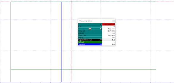
ExpandWhileTrue
ExpandWhileTrue function holds the value of SourceChannel from rising edge of BoolChannel until falling edge of BoolChannel
Syntax |
Meaning |
|---|---|
C1=ExpandWhileTrue(#SourceChannel, #BoolChannel) |
Holds the value of SourceChannel from rising edge of BoolChannel until falling edge of BoolChannel |
Important
If BoolChannel is = 0, resulting channel C1 is also 0
Important
Frequency of the resulting channel C1 corresponds to the fastest frequency of #SourceChannel
Example 1:
Hold first value of Distance2D only as long as IsTrack is > 0.
[Distance2D_ExpandWhileTrue]
Result = ExpandWhileTrue(#Distance2D, #IsTrack)

Example 2:
Determine value of Trigger1 as long as IsTrack > 0.
[ExpandWhileTrue]
Trigger1 = if(#Distance2D, =, 196, 6.4, 0)
Result = ExpandWhileTrue(#Trigger1, #IsTrack)
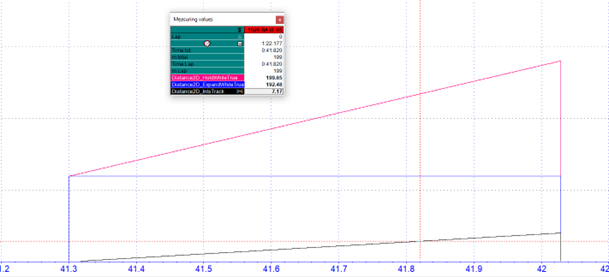
Combine HoldWhileTrue and ExpandWhileTrue
Example:
Show the continuously travelled distance as long as #IsTrack is > 0.
[Distance2D_InIsTrack]
Result =-(#Distance2D_HoldWhileTrue, #Distance2D_ExpandWhileTrue)
DeltaWhileTrue
DeltaWhileTrue function calculates the difference between the values of SourceChannel from rising edge of BoolChannel to falling edge of BoolChannel
Syntax |
Meaning |
|---|---|
C1=DeltaWhileTrue(#SourceChannel, #BoolChannel) |
Calculates the difference between the values of SourceChannel from rising edge of BoolChannel to falling edge of BoolChannel |
Important
If BoolChannel is = 0, resulting channel C1 is also 0
Important
Frequency of the resulting channel C1 corresponds to the fastest frequency of #SourceChannel
InterpolateWhileFalse
The function InterpolateWhileFalse linearly interpolates the values of SourceChannel between falling and rising edge of BoolChannel. Additionally the interpolation can be made dependent on how long BoolChannel is < 1.
Attention
WhileFalse-condition!
Important
This function can be used to eliminate short signal dropouts
Important
Frequency of the resulting channel C1 corresponds to the fastest frequency of #SourceChannel
Syntax |
|---|
C1=InterpolateWhileFalse(#SourceChannel, #BoolChannel) |
C1=InterpolateWhileFalse(#SourceChannel, #BoolChannel, MaxGap) |
Meaning |
The function InterpolateWhileFalse linearly interpolates the values of SourceChannel between the falling and rising edge of BoolChannel. If additionally, a Value MaxGap is given, the interpolation only takes place if BoolChannel was not longer < 1 than the value of MaxGap is. MaxGap is specified in seconds! |
Example:
[V_Sat_Interpol]
Result = InterpolateWhileFlase(#V_GPS, #GPSValid, 2)

InterpolateWhileFalse
Correction of the GPS channel #V_GPS in case of GPS signal dropouts which are shorter than 2 seconds due to e.g. tunnels or trees.
The corrected, green channel #V_Sat_Interpol interpolates the signal at the 1.67 second drop of #GPS_Valid.
Important
This GPS-channel correction is already be implemented in AutoCal-File 2D_GPSAuto.CCF!
InterpolateWhileTrue
The function InterpolateWhileTrue linearly interpolates the values of SourceChannel between rising and falling edge of BoolChannel. Additionally, the interpolation can be made dependent on how long BoolChannel is > 0.
Important
This function can be used to eliminate value gaps that can result from signal failures
Important
Frequency of the resulting channel C1 corresponds to the fastest frequency of #SourceChannel
Syntax |
|---|
C1=InterpolateWhileTrue(#SourceChannel, #BoolChannel) |
C1=InterpolateWhileTrue(#SourceChannel, #BoolChannel, MaxGap) |
Meaning |
The function InterpolateWhileTrue linearly interpolates the values of SourceChannel between rising and falling edge of BoolChannel. If additionally, a Value MaxGap is given, the interpolation only takes place if BoolChannel was not longer < 1 than the value of MaxGap is. MaxGap is specified in seconds! |
Countchanges
The function CountChanges increments the resulting channel C1 by 1 if the difference of SourceChannel compared to the next sample exceeds the StepSize-value.
Important
Only positive StepSize-values are possible!
Syntax |
Meaning |
|---|---|
C1=CountChanges(#SourceChannel, StepSize) |
Incrementing the resulting channel C1 by 1 if the difference of SourceChannel compared to the next sample exceeds the StepSize-value. |
VDVWhileTrue
VDVWhileTrue function calculates the Vibration Dose Value (VDV) of SourceChannel as long as BoolChannel is > 0.
Vibration Dose Value (VDV):
Vibration Dose is a parameter that combines the magnitude of vibration and the time for which it occurs to evaluate the impact of whole-body vibrations. The VDV depends on the integral of the acceleration in the fourth power over time and thus reacts more sensitively to the highest measured values, which are often due to shocks. Therefore, VDV is often used at comfort tests because it is suitable for deciding whether it is dealt with shock excitation.
Syntax |
Meaning |
|---|---|
C1=VDVWhileTrue(#SourceChannel, #BoolChannel) |
Calculating the Vibration Dose Value (VDV) of SourceChannel as long as BoolChannel is > 0. |
Important
If BoolChannel is = 0, resulting channel C1 is also 0
Important
Frequency of the resulting channel C1 corresponds to the fastest frequency of #SourceChannel
RMSWhileTrue
RMSWhileTrue function calculates the Root Mean Square (RMS) of SourceChannel as long as BoolChannel is > 0.
Syntax |
Meaning |
|---|---|
C1=RMSWhileTrue(#SourceChannel, #BoolChannel) |
Calculating the Root Mean Square (RMS) of SourceChannel as long as BoolChannel is > 0. |
Important
If BoolChannel is = 0, resulting channel C1 is also 0
Important
Frequency of the resulting channel C1 corresponds to the fastest frequency of #SourceChannel
Example:
Determine the Root Mean Square of one period of a sinusoidal signal with amplitude 1 and frequency 1 Hz.
[Variables]
Frequency = 1000    ; [Hz]
Amplitude = 1       ; [Hz]
Period    = 1       ; [Hz]

[Sin]
; u(T)  = Û * Sin (2PI * f *t) --> Formular for sinusoidal signal
C0      = const(2, @Frequency)
PI2     = *(#C0, @PI)

C0      = Const(1, @Frequency)
Time    = I(#C0)

C0      = *(period, #Time)
C1      = *(#PI2, #C0)
C2      = Sin(#C1)
Result  = *(@Amplitude, #c2)            ; Create sinusoidal signal

[True]
Result  = If(#Time, <, 1, 1, 0)         ; Create True condition

[RMS]
Result  = RMSWhileTrue(#Sin, #True)     ; Create RMS channel


Result = InterpolateWhileFlase(#V_GPS, #GPSValid, 2)
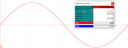
RMSWhileTrue at sinusoidal signal with amplitude 1 and frequency 1 Hz
MOVWhiletrue
MOVWhileTrue function calculates the Movement (MOV) of SourceChannel as long as BoolChannel is > 0.
The MOV command is a command specially developed by 2D-Datarecording with which a change of a signal can be evaluated by the movement coefficient.
The function sums up the absolute difference between two samples of the SourceChannel as long as BoolChannel is > 0. Therefore, a channel is created which is an indicator how a signal is changing over time.
This creates a channel which is an indicator how a signal is changing over time.
Syntax |
Meaning |
|---|---|
C1=MOVWhileTrue(#SourceChannel, #BoolChannel) |
Calculating the Movement Value (MOV) of SourceChannel as long as BoolChannel is > 0. |
Important
If BoolChannel is = 0, resulting channel C1 is also 0
Important
Resulting channel C1 is not reseted at a laptrigger
Important
Frequency of the resulting channel C1 corresponds to the fastest frequency of #SourceChannel
Example 1:
Determine the Movement value of one period of a sinusoidal signal with amplitude 1 and frequency 1Hz.

MOVWhileTrue at sinusoidal signal with amplitude 1 and frequency 1 Hz
This example shows the ideal value of the MOV-function:
Sin |
MOV |
|---|---|
0 –> 1 |
+1 |
1 –> 0 |
+1 |
0 –> -1 |
+1 |
-1 –> 0 |
+1 |
= 4 |
Example 2:
Analysis of the throttle actuation of a driver at one point of a racetrack in different laps.
Important
For this purpose, the same measurement is loaded twice in the Analyzer and superimposed
[True_ThrottleActuation]
Result = if(#Throttle, >, 0.6, 1, 0)

[MOV_ThrottleActuation]
Result = MOVWhileTrue(#Throttle, True_ThrottleActuation)
Code explanation: At first a Boolean condition #True_ThrottleActuation is created which is TRUE if #Throttel is bigger than 0.6%. This Boolean condition is used together with SourceChannel #Throttle to calculate the MOV-value.
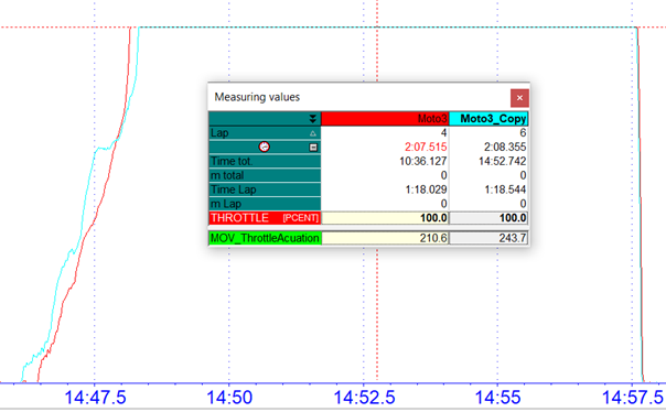
The red measurement Moto3 shows a position of the fastest lap, while the blue measurement Moto3_Copy shows the same position in the following lap. In the fastest lap the driver has opened the throttle very definitely, while in the following lap the throttle was even closed a little bit during the acceleration phase.
These different opening sequences are reflected in the value of the MOV command, which is higher in the blue measurement Moto3_Copy due to the closing of the throttle grip than in the blue measurement Moto3
For example, the throttle grip movement can be classified as better the closer the value of the #MOV_ThrottleActuation is to 200 (ideal value is 200 throttle grip open and closed once).
Important
This command is also suitable for suspension adjustment, as it can be used to analyse the oscillation of the suspension due to a too wide opened rebound
Table functions
Most analogue sensors do have a linear behaviour. That means the output voltage of the sensor is direct proportional to the measured physical value.
The physical value can be calculated by a simple rule of three:
Other sensors like NTC temperature sensors do not have a linear characteristic curve.
In this case, sensor manufacturers provide a specific characteristic curve, which can be translated to a 2D-useable table giving the physical value for all measured voltages.
The table function is used to linearize the measured voltage values to the physical values.
Syntax |
Meaning |
|---|---|
C1=F(#CH, T(TableName.Ext)) |
#CH will be connected to the respective table |
Important
If no extension (.Ext) is given to the table name, TBL is taken as default.
Example 1:
Obtain the power of the engine with RPM using the table linking the power with RPM.
Example 2:
Generate a linear channel from a non-linear one with the calibration sheet you get from the manufacturer (e.g. lambda sensor).
Storage location of tables:
If no specific path to the respective table TableName.EXT is specified, the system searches in the respective event.
If a calculation is then carried out for the first time with this table, CalcTool copies the table into the MES directory of the measurement currently being used when executing the table function. CalcTool accesses this table in the MES directory for all further executions!
If a modification is made to the table used, the table in question should be deleted from any MES directory already in use and the table replaced if necessary.
Important
If no specific path to the respective table TableName.EXT is specified, the system searches in the respective event. if the table is not in the respective event, the known placeholders from chapter 2D directories can also be used.
2D-table function
The 2D-table function can be seen as the further development of the normal table function shown before, because the 2D-table connects a second channel to a table.
Syntax |
Meaning |
|---|---|
C1=F(#CH1, #CH2, T(TableName.Ext, IntType)) |
#CH1 and #CH2 will be connected to find corresponding value in table “TableName.Ext” |
#CH1 corresponds to the first row of the table TableName.Ext
#CH2 corresponds to the first column of the table TableName.Ext
#C1 is the resulting table value and depends on the values of #CH1 and #CH2
IntType (Type of Interpolation) |
|
|---|---|
LIN |
Linear Interpolation |
Attention
This function necessarily needs the CSV as table format!
Attention
Column separation character must be a semicolon “;”
Attention
Decimal separation character must be a point “.” (½ = 0.5)
Important
CSV files can be created with simple text editor or with MS Excel™
Examples:
The radius of a wheel of a motorcycle is a function depending on the banking angle of the bike and the speed. The higher the banking angle is, the lower is the effective radius of the wheel (in fact the size of the wheel is the same, but the distance between the axe centre and the point where the wheel touches the ground becomes smaller).
The faster a wheel rotates, the higher is the rotational energy and the tire expands a bit.
The 2D-table formula for this calculation is:
[RadiusOfWheel]
Result = F(#Speed, #Banking, T(WheelRadius.CSV, Lin))
This is an example for a table returning the radius of a wheel as a function of the speed and the banking angle of a bike:
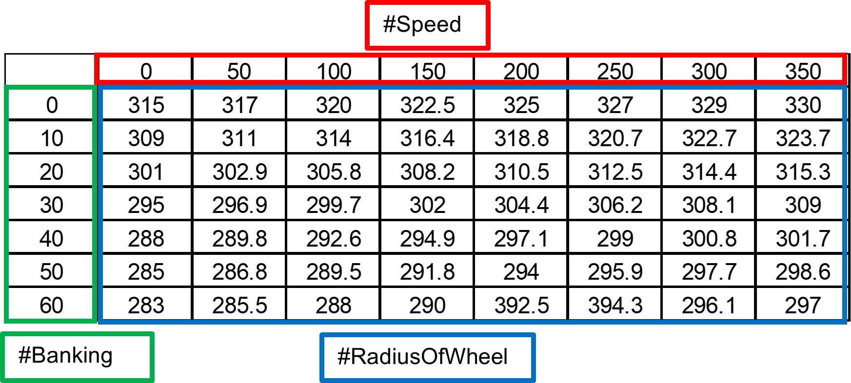
For example, radius of the wheel at a speed of 100 km/h and an angel of 20° is 305.8.
When CalcTool tries to find a value depending on speed and banking angle, it searches for the columns and row that frames speed and the banking angle.
Then a linear interpolation is performed to calculate the value.
Example 1:
#Speed is assumed as 110 km/h
#Banking is assumed as 33°

The 2D-table function internally calculates a percentage graded (linear interpolated) table to find the intermediate value:
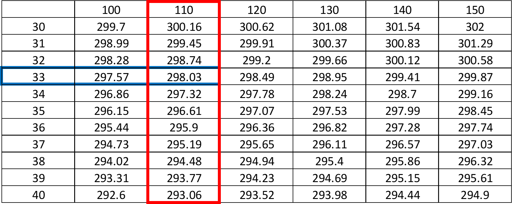
The resulting radius of the wheel would be 298.03.
In the following figure, it can be seen how the table looks, if it is created via an Editor:
Example 2:
#Speed is assumed as 360 km/h
#Banking is assumed as 60°
The resulting radius of the wheel would be 297.
2D-table search function
CalcTool provides a kind of inverse function for the 2D-table function. It uses the same type of table files like the function above.
Syntax |
|---|
C1=T2DSearch(#CH1, #CH2, T(TableName.Ext, IntType), [SearchDirection]) |
Meaning |
#CH1 and #CH2 will be used to find corresponding value in the table “TableName.Ext |
#CH1 corresponds to the table values of the table TableName.Ext
#CH2 corresponds to the first column of the table TableName.Ext
#C1 corresponds to the first row of table TableName.Ext and is approximated by #CH1 and #CH2
The T2DSearch function interpolates linearly between given values.
IntType (Type of Interpolation) |
|
|---|---|
LIN |
Linear Interpolation |
SearchDirection |
|
|---|---|
Left |
Searching table from left to right |
Right |
Searching table from right to left |
Example:
[Speed]
Result = T2DSearch(#RadiusOfWheel, #Banking, T(WheelRadius.CSV, Lin))
#Banking is assumed as 33°.
#RadiusOfWheel is assumed as 298.03mm.

The corresponding #Speed is 110 km/h.
3D-table function
Like the 2D-table function CalcTool provides a 3D-table function.
This function can be used similar to the 2D table function, the only difference is that the table used depends on the value of the third channel #CH3.
Syntax |
Meaning |
|---|---|
C1= F(#CH1, #CH2, #CH3, T(TableName.Ext, IntType)) |
#CH1 and #CH2 will be used to find corresponding value in through #CH3 defined table TableName.Ext |
#CH1 corresponds to the first row of the table TableName.Ext
#CH2 corresponds to the first column of the table TableName.Ext
#CH3 corresponds to the name of the used table
#C1 is the resulting table value and depends on the values of #CH1 and #CH2 and the used table
IntType (Type of Interpolation) |
|
|---|---|
LIN |
Linear Interpolation |
Example:
The torque that an engine delivers to a wheel is dependent on the selected gear, the engine revolutions, and the throttle position.
[Torque]
Result = F(#Gear, #RPM, #Throttle, T(Torque_at_*.CSV, Lin))
You can see in the example that the filename of the table contains an asterisk (“*”).
Depending on the value of channel #throttle a different table is used.
Different tables can be used:
Torque_At_0.CSV
Torque_At_20.CSV
Torque_At_40.CSV
Torque_At_50.CSV
Torque_At_60.CSV
Torque_At_70.CSV
Torque_At_80.CSV
Torque_At_90.CSV
Torque_At_100.CSV
Depending on the throttle grip positions 0, 20, 40, 50, 60, 70, 80, 90 and 100 %., the respective table is then used for the table calculation
CalcTool makes a linear interpolation for each value of #Throttle, #Gear and #RPM.
Changing the storage type
Reasons why the data type must be changed:
Other functions expect word channel for input
Save memory on hard disk
The following data types are usable:
Word
Binary
LongInt
Single
Double
Signed
Unsigned
Important
Most channels in a 2D system are recorded as 16-bit integer values (what is called a word) combined
Important
Channels created by the calculation tool are stored as float values (single precision with 32 bit) which need the double space on the hard disk of the computer.
Important
Data type can be seen in Formel editor (Analyzer Functions Formel Editor)
Attention
Changing data type might lowers precision of a channel!
WORD-function
If the Word-function is used with only one parameter (a channel), CalcTool determines the minimum and the maximum value of the original channel. The formula is calculated that the minimum is transformed to 0 and the maximum to 65535 (maximum word).
In some cases, it is helpful to use other values. If the signal has spikes you might use your own border values.
Important
Values higher than the upper border are set to the upper border value.
Important
Values lower than the lower border are set to the lower border value.
The third possibility to use the Word-function is to give the step (the accuracy) which should be used for one digit. The minimum value for the resulting channel is the smallest value of the input channel and the maximum 65535 multiplied with this step added to that minimum.
Syntax |
Meaning |
|---|---|
C1=Word(#CH) |
Changing data type of #CH to WORD and set limits of resulting channel to minimum and maximum of channel |
C1=Word(#CH, LowerBorder, UpperBorder) |
Changing data type of #CH to WORD and set limits of resulting channel to LowerBorder and UpperBorder |
C1=Word(#CH, Step) |
Changing data type of #CH to WORD and set limits of resulting channel to minimum and [65535 * Step + minimum] |
Example:
[Speed_WORD]
Result = Word(#Speed, 0.01)
The resulting channel has an accuracy of 0.01, the minimum value is 0 and the maximum is 655.35.
BINARY-function
the binary command is very similar to the word command and can be seen as an extension, because with binary borders and accuacy of a channel can be set simultaneously.
Syntax |
Meaning |
|---|---|
C1=Binary(#CH, Range) |
Changing data type of #CH to WORD and determination of accuracy with actual channel borders |
C1=Binary(#CH, Range, LowerBorder, UpperBorder) |
Changing data type of #CH to WORD and determination of accuracy with respective channel borders |
Important
A Binary-function with the range 65536 (0…65535) has the same result as a word function would have.
Important
Values higher than the upper border are set to the upper border value.
Important
Values lower than the lower border are set to the lower border value.
Example:
[Acc_x_Bin]
Result = Binary(#Acc_x_rot, 1024, -160, 160)
All values outside the borders -160 and +160 are set to the respective border values and the resulting channel is a Word channel with an accuracy of 320/1024=0.03125.
Long Int
Set data type to LongInt.
Syntax |
Meaning |
|---|---|
C1=LongInt(#CH) |
Changing data type of #CH to LongInt and set limits of resulting channel to minimum and maximum of channel |
C1=LongInt(#CH, LowerBorder, UpperBorder) |
Changing data type of #CH to LongInt and set limits of resulting channel to LowerBorder and UpperBorder |
C1=LongInt(#CH, Step) |
Changing data type of #CH to LontInt and set limits of resulting channel to minimum and [65535 * Step + minimum] |
Single-precision float
Set data type to single-precision float (32-bit).
Syntax |
Meaning |
|---|---|
C1=Single(#CH) |
Changing data type of #CH to single-precision float |
Double precision float
Set data type to double-precision float (64-bit).
Syntax |
Meaning |
|---|---|
C1=Double(#CH) |
Changing data type of #CH to double-precision float |
Signed function
Attention
Input channel must be an unsigned integer channel, that means Byte, Word or Double Word (=DWord) format
Syntax |
Meaning |
|---|---|
C1=Signed(#CH) |
Changing range of #CH from unsigned to signed |
Examples: |
|||
|---|---|---|---|
Type |
Signed range |
Unsinged range |
|
Byte: |
0…255 |
-127…128 |
|
Word: |
0…65535 |
-32767…+32768 |
|
DWord |
0…4294967295 |
-214748367…+214748368 |
|
UnSigned function
Attention
Input channel must be an unsigned integer channel, that means Byte, Word or Double Word (=DWord) format
Syntax |
Meaning |
|---|---|
C1= UnSigned(#CH) |
Changing range of #CH from signed to unsigned |
Examples: |
|||
|---|---|---|---|
Type |
Unsigned range |
Signed range |
|
Byte: |
-127…128 |
0…255 |
|
Word: |
-32767…+32768 |
0…65535 |
|
DWord |
-214748367…+214748368 |
0…4294967295 |
|
Changing byte-order of channel
Some 2D data acquisition systems provide the possibility to record CAN-bus identifier which transfer data information between vehicle systems like ECU or ABS. To record this transferred data, byte-information must be set in communication software to determine which data from CAN-bus should be recorded. If the byte order of recorded channels is incorrect the resulting channel will be unusable.
Important
The SWAP-function was designed to change the byte order of CAN-bus channels
Important
Input channel with data type Word or LongInt are expected as input
Syntax |
Meaning |
|---|---|
C1= Swap(#CH) |
Changing byte-order of channel #CH |
Additional channel information
Dimension
To change the dimension of a channel, use the Set-function.
Important
Only at integration and derivation of speed and distance, channel dimension is set automatically
Important
At all other calculations, the resulting channel receives the dimension of first input channel!
Important
Dimension can be seen in channel list and measurement mode
Syntax |
Meaning |
|---|---|
C1=SET(DIM=’Value’) |
Set dimension of channel #C1 to Value |
Example:
Set the dimension of a calculated gear channel to ’Gear’
Gear = Set(Dim='Gear')
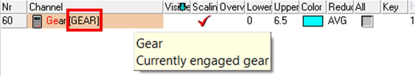
Set dimension
Sensorinfo
To add the additional information to a channel, use the Set-function.
Important
Only at integration and derivation of speed and distance, channel dimension is set automatically
Important
At all other calculations, the resulting channel receives the dimension of first input channel!
Important
Sensorinfo is displayed when cursor is put on respective channel in channel list!
Syntax |
Meaning |
|---|---|
C1=SET(Sensorinfo=’Text’) |
Set additional Sensorinfo of channel #C1 |
Example:
Set the Sensorinfo of a calculated gear channel to ’Gear’
Gear = Set(Sensorinfo='Currently engaged gear')
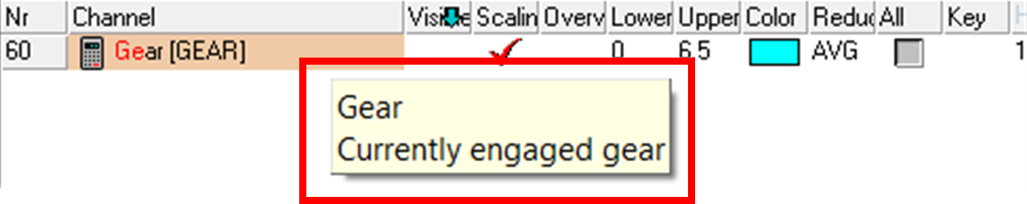
Set Sensorinfo
Channel handling
Deleting channels
Function to delete channels, which were created by a previous calculation.
Syntax |
Meaning |
|---|---|
Delete(#CH) |
Delete selected #CH |
Attention
It is not possible to delete channels, which were recorded by the data acquisition system
Important
Wildcard character “*” can be used Delete(#*) deletes all channels created by CalcTool
Hiding channels
Function to hide a channel. A hidden channel is present but not visible in the software.
Syntax |
Meaning |
|---|---|
Hide(#CH) |
Hide selected #CH |
Unhiding channels
Function to unhide a hidden, but still present channel.
Syntax |
Meaning |
|---|---|
Unhide(#CH) |
Unhide selected #CH |
Restoring channels
If a originally recorded channel was overwritten by NewResult (see 0), the originally recorded channel can be restored with this command.
Syntax |
Meaning |
|---|---|
Restore(#CH) |
Restore selected #CH |
NoOperation
Linking all values of a channel without further processing to the resulting channel.
Syntax |
Meaning |
|---|---|
C1=NoOp(#CH) |
Link #CH to resulting channel C1 |
Laps
Important
Laptimes can be created either during by special logger settings or afterwards during data evaluation with the following functions!
Important
Laptriggers can also be useful for development purposes, e.g. if Laptriggers are generated for certain events like gear changes. Page-up and page-down keys can then be used to jump back and forth between the Laptriggers and thus every gear change.
!!!Link!!! +————–+—————————————————————————————————————————–+ | | - For more information about how to create Lap- and Section-times, please see the Manual GPS_Laptime on your website: | | | | | | http://2d-datarecording.com/downloads/manuals/ | +==============+=============================================================================================================================+ +————–+—————————————————————————————————————————–+
Create lap trigger by channel
If there are no recorded lap triggers in measurement, they can be created afterwards.
Important
A trigger is set at each position where the value of the input channel changes! Summarizing boolean events with the sum function is particularly useful!
Attention
Those laptriggers can be reseted via Analyzer File Restore original laptrigger
Syntax |
Meaning |
|---|---|
C1=SetLapTrigger(#CH) |
Creates lap triggers depending on #CH |
C1=SetLapTrigger(#CH, Timeout) |
Creates lap triggers depending on #CH and with a defined Timeout in seconds in which no other lap trigger will be set |
If laptriggers created by CalcTool, the laptriggers can be deleted via Analyzer menu File

Delete (Restore) Laptriggers in Analyzer
Attention
Laptriggers created while recording from logger can only overwritten but never deleted completely and restored every time via shown button!
Create lap trigger by line
If there are no recorded lap triggers in measurement, they can be created afterwards.
Attention
Function compares current Lat- and Lon-Positions with first in Event-folder founded line file
Syntax |
Meaning |
|---|---|
C1= CreateLapTriggerByLine(#CH_Lat, #CH_Lon, Radius) |
Creates lap triggers depending on the distance of Latitude/Longitude channels to line file entries in respect to Radius |
Create Laptimes
With the function MakeLaptimeCh a channel is created which contains the laptimes in seconds.
Important
For creating a laptime channel, lap trigger must be available!
Important
Laptime always corresponds to the previous lap!
Syntax |
Meaning |
|---|---|
C1=MakeLaptimeCH(Rate) |
Creating a channel with the laptimes in seconds of the previous lap with defined Rate |
Example:
Lap |
Actual laptime |
Channel value |
|---|---|---|
1 |
2:25:210 |
0 |
2 |
1:59.482 |
145.2 |
3 |
1:56.795 |
119.5 |
Sections
Important
Lap can be divided into sections for more precise evaluation.
Important
Section times can be created either during by special logger settings or afterwards during data evaluation with the following functions!
Attention
To create Sections, lap triggers must already be available!
!!!Link!!!
|
Create section trigger by channel
If there are no recorded section triggers in measurement, they can be created afterwards.
Important
A trigger is set at each position where the value of the input channel changes! Summarizing boolean events with the sum function is particularly useful!
Attention
Those section triggers can be reseted via Analyzer File Restore original section trigger
Syntax |
Meaning |
|---|---|
C1=SetSecTrigger(#CH) |
Creates section triggers depending on #CH |
C1=SetSecTrigger(#CH, Timeout) |
Creates section triggers depending on #CH and with a defined Timeout in seconds in which no other section trigger will be set |
Create Sectiontimes
With the function MakeSectimeCh a channel is created which contains the section times in seconds.
Attention
For creating a section time channel, section trigger must be available!
Attention
Section time always corresponds to the previous section!
Syntax |
Meaning |
|---|---|
C1= MakeSectimeCh(Rate) |
Creating a channel with the section times in seconds of the previous section with defined Rate. |
Bike and car physical formulas
Speed
The logger calculates the speed by using the digital signal from the speed sensor, the tire-dimension and the number of pulses for the turning wheel.
Slow wheel speeds cause a problem of inaccuracy in the measurement of wheel speed. This inaccuracy at low wheel speeds is corrected by the command Speed_L4 when generating the speed via the wheel speed sensor principle.
Syntax |
Meaning |
|---|---|
C1=Speed_L4 (#CH) |
#CH: input channel (Normally a speed channel) |
Attention
Do not use this function on filtered values
Attention
Do not use this function in combination with tables
Example:
Speed_Rear = Speed_L4(#VRear)
Speed2
This function is used to calculate a major speed channel from two separately measured speeds. The result is the average of the two speeds. If the difference between the two channels is greater than 10%, the resulting value is the greater signal.
Syntax |
Meaning |
|---|---|
C1=Speed2 (#CH1,#CH2) |
Input channels #CH1 and #CH2 (Normally two speed channels) |
Example:
Speed_Rear = Speed2(#V_Front, #VRear)
Attention
Do not use this function on filtered values.
Attention
Do not use this function in combination with tables
Attention
Use this function only with speed-channels
Slip
This function allows you to calculate the percentage of the vehicle’s slip between front and rear wheel.
Attention
Front and rear speed must be provided for this function!
Syntax |
Meaning |
|---|---|
C1=Slip (#CH_Front, #CH_Rear) |
Calculating percentage of vehicles slip between front and rear wheel |
Banking
Important
This function must be used to calculate the banking angle of the bike with the gyro channel.
The gyro measures the banking angle speed of the bike. So, if the result of the integration of this singal is the inclination of the bike. But with this kind of sensor, a small error can lead to a totally wrong result.
To correct this, the function integrates the gyro’s signal with a linear regression to avoid that the result is modified by the error explained above.
For example, considering we’ve got a gyro measuring a range of 300° (from –150° to 150°) with 4095 bits. So, 0° will be at 2047 or 2048 bits. This means there is an error of ½ bit.
Assuming a lap lasts 2 minutes and sampling rate is 50 Hz. Therefore, there are 6000 samples per lap. As mentions above, each sample contains an error of ½ bit.
Thus, the total error is ½ * 6000 = 3000 bits.
But for 1 bit you have approximately 0.1° (300/4095) of error.
Finally, your error will reach 300° by lap.
Syntax |
Meaning |
|---|---|
C1=Banking (#AGyro, P1) |
Respective Inclination-Gyro-Channel #CH. P1 is the angle of the bike on the start/finish line. |
Important
Use 0 for P1 if bike is straight on finish line
BANK2ACC function
It is not worth measuring lateral acceleration on a bike.
However, to use the racetrack calculation function (Analyzer Functions Circuit), a “virtual” lateral acceleration is required.
This function calculates the lateral acceleration of the bike from the inclination of the bike calculated with banking function.
Syntax |
Meaning |
|---|---|
C1= BANK2ACC (#Abanking) |
#Abanking is the channel where the inclination of the motorcycle is calculated with the banking channel |
Roll angle
This function calculates the roll angle of a bike from two accelerometers and two gyros.
Important
The roll angle describes the movement around the x-axis (longitudinal direction of the vehicle).
Syntax |
Meaning |
|---|---|
C1= RollAngle (#AccY, #AccZ, #GyroX, #GyroZ) |
This function calculates the roll angle |
Execute external programs
Important
In chapter 2D directories an overview over different path-placeholders can be found which can replace … in the path calls like …\FileName.BAT
Execute
By using Execute-function, external CommandLine-programs and thus Batch-Files can be executed via CalcTool.
Important
When executing the Execute function the following CalcTool calculations are stopped as long as the external program is executed!
Syntax |
Meaning |
|---|---|
Execute(CommandLine , Param1, …) |
Start external program defined by Commandline Parameters to pass to the program are given separated by commas |
If additional functions are required which are not already included in our Software, please contact us via Info@2D-datarecording.com
Example:
At every execution of a CAL-file, the file C:\ECU\CurrentSetting.bat must be copied to the respective event folder.
[RunExternal]
Execute(c:\Race\CopyEcuFile.bat, <MesDir>)
When executing the CAL-File which contains the previous call, first CalcTool replaces the placeholder <MesDir> (see 2D directories) and then passing over the respective path to the Batchfile CopyEcuFile.bat.
Inside the handed over path is implemented with %1. A second handover parameter would be passed over with %2.
CopyEcuFile.bat:
copy C:\ECU\CurrentSetting.bat %1
ExecuteNoWait
By using Execute-function, external CommandLine-programs and thus Batch-Files can be executed via CalcTool.
Important
When executing the ExecuteNoWait function the following CalcTool calculations will not be stopped as long as the external program is executed!
Important
For every ExecuteNoWait-command a new [Group] must be used
Syntax |
Meaning |
|---|---|
ExecuteNoWait(CommandLine, Param1, …) |
Start external program defined by Commandline Parameters to pass to the program are given separated by commas |
Attention
If additional functions are required which are not already included in our Software, please contact us via Info@2D-datarecording.com
Execution of CAL-files
FlushFiles
Syntax |
Meaning |
|---|---|
FlushFiles |
At point in code the already calculated channels of the calculation file will be outputted during execution |
Important
Can be helpful at calling external programs from CAL-file (see here).
FlushQuiet
Syntax |
Meaning |
|---|---|
FlushQuiet |
The command described above is executed without user message. |
QuietMode
Disabling the report function shown below, when executing a CAL-file.

QuietMode enabled
Syntax |
Meaning |
|---|---|
QuietMode |
Disabling the report function. |
Important
Command can be called anywhere in the code and is valid for the whole CAL-file
Error handling
Show no errors
Disabling the error report function shown below, when an error occurs at executing a CAL-file.
Syntax |
Meaning |
|---|---|
ShowNoErrors |
Disabling the error report function. |
Error report enabled
Attention
Use only, when sure, that no errors occur!
Important
Command can be called anywhere in the code and is valid for the whole CAL-file
When an error occurs in the calculation it sometimes makes no sense to continue calculating after the error, because all following calculations depend on the error free results of previous lines.
For this purpose, CalcTool provides three different abort commands.
Abort calculation of group when an error occurred
Syntax |
Meaning |
|---|---|
OnErrorExitGroup |
Stop executing the calculation of the current group if an error occurred |
The calculation of the current group is aborted when an error occurred.
Channels calculated before are saved.
CalcTool continues with the next group.
Abort whole calculation when an error occurred
Syntax |
Meaning |
|---|---|
OnErrorExitTotal |
Stop executing the calculation of the whole CAL-file if an error occurred. |
The calculation of the current group is aborted when an error occurred.
Channels calculated before are saved.
CalcTool does not continue with the next group.
Abort whole calculation
Syntax |
Meaning |
|---|---|
ExitTotal |
Stop executing the calculation of the whole CAL-file. |
Calculating the current group is aborted even if there was no error before this command.
Channels calculated before are saved.
CalcTool does not continue with the next group.
Table of all calculation functions
C1=+(#CH1, #CH2) |
|
|---|---|
C1=+(#CH, Constant) |
|
C1=-(#CH1, #CH2) |
|
C1=-(#CH, Constant) |
|
* |
C1=*(#CH1, #CH2) |
C1=*(#CH, Constant) |
|
/ |
C1=/(#CH1, #CH2) |
C1=/(#CH, Constant) |
|
{$I |
{$I …\FileName.EXT} |
{$I |
{$IfExists(#CH) …\FileName.CAL, P(P1, P2, …)} |
{$I |
{$IfLaptimesExist …\FileName.CAL, P(P1, P2, …)} |
{$I |
{$IfLicenceNameContains(‘Name’) …\FileName.CAL, P(P1, P2, …)} |
{$I |
{$IfNotExists(#CH) …\FileName.CAL, P(P1, P2, …)} |
{$I |
{$IfNotLaptimesExist …\FileName.CAL, P(P1, P2, …)} |
{$I |
{$IfNotLicenceNameContains(‘Name’) …\FileName.CAL, P(P1, P2, …)} |
{$I |
{$IfNotSpecIs(Group.Entry, ‘Value’) …\FileName.CAL, P(P1, P2, …)} |
{$I |
{$IfNotSpecValueContains(Group.Entry, ‘Value’) …\FileName.CAL, P(P1, P2, …)} |
{$I |
{$IfNotSpecValueExists(Group.Entry) …\FileName.CAL, P(P1, P2, …)} |
{$I |
{$IfSpecIs(Group.Entry, ‘Value’) …\FileName.CAL, P(P1, P2, …)} |
{$I |
{$IfSpecValueContains(Group.Entry, ‘Value’) …\FileName.CAL, P(P1, P2, …)} |
{$I |
{$IfSpecValueExists(Group.Entry) …\FileName.CAL, P(P1, P2, …)} |
Abs |
C1=Abs(#CH) |
And |
C1=AND(#CH1,#CH2) |
C1=AND(#CH, Constant) |
|
ArcCos |
C1=arccos(#CH) |
ArcSin |
C1=arcsin(#CH) |
ArcTan |
C1=arctan(#CH) |
ArcTan2 |
C1=arctan2(#CH1, #CH2) |
AvgValue |
C1= AvgValue(#CH, Rate) |
AvgWhileTrue |
C1=AvgWhileTrue(#SourceChannel, #BoolChannel) |
Bank2Acc |
C1=BANK2ACC (#Abanking) |
Banking |
C1=Banking (#AGyro, P1) |
Binary |
C1=Binary(#CH, Range) |
C1=Binary(#CH, Range, LowerBorder, UpperBorder) |
|
ChannelArray |
C1=ChannelArray(‘Name_VAR1’, ‘Name_VAR2’, ‘Name_VAR3’) |
Const |
C1=Const(Value, Rate) |
Cos |
C1=cos(#CH) |
CountChanges |
C1=CountChanges(#SourceChannel, StepSize) |
CountValue |
C1=CountValue(#CH, value, tolerance) |
CreateLapTriggerByLine |
C1= CreateLapTriggerByLine(#CH_Lat, #CH_Lon, Radius) |
DCos |
C1=dcos(#CH) |
DecWhileTrue |
C1=DecWhileTrue(#SourceChannel, #BoolChannel) |
Delete |
Delete(#CH) |
DeltaWhileTrue |
C1=DeltaWhileTrue(#SourceChannel, #BoolChannel) |
Derivate |
C1=F’(#CH) |
C1=Derivate(#CH) |
|
Div |
C1=Div(#CH1, #CH2) |
C1=Div(#CH, Constant) |
|
Double |
C1=Double(#CH) |
DSin |
C1=dsin(#CH) |
DTan |
C1=dtan(#CH) |
EnterChannel |
C1=EnterChannel(‘Text shown in dialog’) |
C1=EnterChannel(‘Text Text shown in dialog’’, #CH) |
|
EnterValue |
C1=EnterValue(‘Text shown in dialog’) |
C1=EnterValue(‘Text shown in dialog’’, Value) |
|
EnvMax |
C1=EnvMax(#CH, samples number) |
EnvMin |
C1=EnvMin(#CH, samples number) |
Execute |
Execute(CommandLine , Param1, …) |
ExecuteNoWait |
ExecuteNoWait(CommandLine, Param1, …) |
ExecutePreProcessor |
ExecutePreprocessor |
ExitTotal |
ExitTotal |
Exp |
C1=Exp(#CH) |
ExpandWhileTrue |
C1=ExpandWhileTrue(#SourceChannel, #BoolChannel) |
F |
C1=F(#CH, F(CrossFrequency)) |
C1= F(#CH, F(FilterType WindowType CrossFrequency NumberOfIterations)) |
|
C1=F(#CH, F( FilterType #DepthChannel)) |
|
FallingEdge |
C1=FallingEdge(#CH) |
FillFromBool |
C1=FillFromBool(#SourceChannel, #BoolChannel) |
FillWithNextBool |
C1=FillWithNextBool(#SourceChannel, #BoolChannel) |
FindGPSFreq |
C1= FindGPSFreq(#GPS_Channel) |
FirstValue |
C1=FirstValue(#CH, Rate) |
Floor |
C1= Floor (#CH) |
FlushFiles |
FlushFiles |
FlushQuiet |
FlushQuiet |
Freq |
C1=Freq(#CH, NewRate) |
FreqBase |
C1=FreqBase(#CH, NewRate, GPSRate) |
FreqNI |
C1=FreqNI(#CH, NewRate) |
GPSShift |
C1=GPSShift(#GPSChannel, #ShiftChannel, NewFreq) |
Hide |
Hide(#CH) |
HoldWhileTrue |
C1=HoldWhileTrue(#SourceChannel, #BoolChannel) |
If |
C1=if(#CH, Operator, #CH, TrueResult, FalseResult) |
C1=if(#CH, Operator, Constant , TrueResult, FalseResult) |
|
IfExists |
IfExists(#CH) |
IfLaptimesExist |
IfLaptimesExist |
IfLicenceNameContains |
IfLicenceNameContains(LicenceName) |
IfNotExists |
IfNotExists(#CH) |
IfNotLaptimesExist |
IfNotLaptimesExist |
IfNotLicenceNameContains |
IfNotLicenceNameContains(LicenceName) |
IfNotSpecValueContains |
IfNotSpecValueContains(Group.Entry, SearchStr) |
IfNotSpecValueExists |
IfNotSpecValueExists(Group.Entry) |
IfNotSpecValueIs |
IfNotSpecValueIs(Group.Entry, SearchValue) |
IfSpecValueContains |
IfSpecValueContains(Group.Entry, SearchStr) |
IfSpecValueExists |
IfSpecValueExists(Group.Entry) |
IfSpecValueIs |
IfSpecValueIs(Group.Entry, SearchValue) |
IIR-Lowpass |
C1=F(#CH,F(IIR(CrossFrequency HZ))) |
Integer formular |
C1=F(#CH, I(Multiplicand,Divisor,Offset)) |
Integrate |
C1=Integrate(#CH) |
C1=Integrate(#CH , Value) |
|
InterpolateWhileTrue |
C1=InterpolateWhileTrue(#SourceChannel, #BoolChannel) |
C1=InterpolateWhileTrue(#SourceChannel, #BoolChannel, MaxGap) |
|
InterpolateWhileFalse |
C1=InterpolateWhileFalse(#SourceChannel, #BoolChannel) |
C1=InterpolateWhileFalse(#SourceChannel, #BoolChannel, MaxGap) |
|
LastValue |
C1=LastValue(#CH, Rate) |
Limit |
C1=Limit(#CH, minLimit, maxLimit) |
Log |
C1=Log(#CH) |
LongInt |
C1=LongInt(#CH) |
C1=LongInt(#CH, LowerBorder, UpperBorder |
|
C1=LongInt(#CH, Step) |
|
Madgwick_AHRS_IMU |
C1=Madgwick_AHRS_IMU(#GYRO_x, #GYRO_y, #GYRO_z, #ACC_x_1, #ACC_y, #ACC_z, Value) |
Make32 |
C1=Make32(#CHHi, #CHLo) |
Make32GPS |
C1=Make32GPS(#CH) |
Make64 |
C1=MAKE64(#CHHi, #CHLo) |
MakeDouble |
C1=MakeDouble(#CHHi, #CHLo) |
MakeGPS |
C1=MakeGPS(#CHHi, #CHLo) |
MakeLaptimeCh |
C1=MakeLaptimeCH(Rate) |
MakeSectimeCh |
C1=MakeSectimeCh(Rate) |
MakeSingle |
C1=MakeSingle(#CHHi, #CHLo) |
Max |
C1=Max(#CH1, #CH2) |
MaxHoldWhileTrue |
C1=MaxHoldWhileTrue(#SourceChannel, #BoolChannel) |
MaxValue |
C1=MaxValue(#CH, Rate) |
MaxWhileTrue |
C1=MaxWhileTrue(#SourceChannel, #BoolChannel) |
Mileage |
|
Min |
C1=Min(#CH1, #CH2) |
MinHoldWhileTrue |
C1=MinHoldWhileTrue(#SourceChannel, #BoolChannel) |
MinValue |
C1=MinValue(#CH, Rate) |
MinWhileTrue |
C1=MinWhileTrue(#SourceChannel, #BoolChannel) |
Mod |
C1=Mod(#CH1, #CH2) |
C1=Mod(#CH, constant) |
|
MovWhileTrue |
C1=MOVWhileTrue(#SourceChannel, #BoolChannel) |
MUX |
C1=MUX(#DataChannel, #MuxChannel, MuxVal) |
NAnd |
C1=NAND(#CH1,#CH2) |
C1=NAND(#CH, Constant) |
|
NewMainFreq |
NewMainFreq(NewRate) |
NewResult |
|
NoOp |
C1=NoOp(#CH) |
Not |
C1=Not(#CH) |
OnErrorExitGroup |
OnErrorExitGroup |
OnErrorExitTotal |
OnErrorExitTotal |
Or |
C1=Or(#CH1, #CH2) |
C1=Or(#CH1, Constant) |
|
PeakPreView |
C1=PeakPreview(#CH, FallbackThresholdNumber) |
PosMaxWhileTrue |
C1=PosMaxWhileTrue (#SourceChannel, #BoolChannel) |
PosMinWhileTrue |
C1=PosMinWhileTrue(#SourceChannel, #BoolChannel) |
Power |
C1=Power (#CH1, #CH2) |
C1=Power (#CH, Constant) |
|
QuietMode |
QuietMode |
RcLp |
C1=RCLP(#CH, Rate) |
Real formular |
C1=F(#CH, R(Factor, Offset)) |
Restore |
Restore(#CH) |
Result |
|
RisingEdge |
C1= RisingEdge(#CH) |
RMSWhileTrue |
C1=RMSWhileTrue(#SourceChannel, #BoolChannel) |
Roll Angle |
C1= RollAngle (#AccY, #AccZ, #GyroY, #GyroZ) |
Rot_3D_XYZ |
C1=Rot_3D_XYZ(#SourceCH1, #SourceCH2, #SourceCH3, Angle1, Angle2, Angle3) |
Rot_3D_XYZ_Var |
C1=Rot_3D_XYZ_Var(#SourceCH1, #SourceCH2, #SourceCH3, #RotateCH1, #RotateCH2, #RotateCH3 |
Rot_3D_ZYX |
C1=Rot_3D_ZYX(#SourceCH1, #SourceCH2, #SourceCH3, Angle1, Angle2, Angle3) |
Rot_3D_ZYX_Var |
C1=Rot_3D_ZYX_Var(#SourceCH1, #SourceCH2, #SourceCH3, #RotateCH1, #RotateCH2, #RotateCH3 |
Round |
C1=Round (#CH) |
SaveTemporaryChannels |
|
Set |
C1=SET(DIM=’Value’) |
C1=SET(Sensorinfo=’Text’) |
|
SetLapTrigger |
C1=SetLapTrigger(#CH) |
C1=SetLapTrigger(#CH, Timeout) |
|
SetSecTrigger |
C1=SetSecTrigger(#CH) |
C1=SetSecTrigger(#CH, Timeout) |
|
Shift |
C1=Shift(#CH, Constant) |
C1=Shift(#CH, Constant sec) |
|
ShowNoErrors |
ShowNoErrors |
Sig |
C1=Sig(#CH) |
Signed |
C1=Signed(#CH) |
Sin |
C1=sin(#CH) |
Single |
C1=Single(#CH) |
Slip |
C1=Slip (#CH_Front, #CH_Rear) |
SOD |
C1=SOD(#HHMM, #SSHH) |
Speed_L4 |
C1=Speed_L4 (#CH) |
Speed2 |
C1=Speed2 (#CH1,#CH2) |
SQRT |
C1=SQRT(#CH) |
Sum |
C1=Sum(#CH) |
C1=Sum(#CH , Value) |
|
Swap |
C1= Swap(#CH) |
T |
C1=F(#CH, T(TableName.Ext)) |
T2D |
C1=F(#CH1, #CH2, T(TableName.Ext, IntType)) |
T2DSearch |
C1=T2DSearch(#CH1, #CH2, T(TableName.Ext, IntType), [SearchDirection]) |
T3D |
C1= F(#CH1, #CH2, #CH3, T(TableName.Ext, IntType)) |
Tan |
C1=tan(#CH) |
TimeForTrue |
C1=TimeforTrue(#CH) |
TimeSinceTrue |
C1=TimeSinceTrue(#CHl) |
Trunc |
C1=Trunc(#CH) |
UnHide |
Unhide(#CH) |
UnSigned |
C1= UnSigned(#CH) |
UseBits |
C1=UseBits(#DataChannel, MaskValue) |
VCount |
C1= VCount(#CH) |
VDVWhileTrue |
C1=VDVWhileTrue(#SourceChannel, #BoolChannel) |
Word |
C1=Word(#CH) |
C1=Word(#CH, LowerBorder, UpperBorder) |
|
C1=Word(#CH, Step) |
|
Xor |
C1=Xor(#CH1, #CH2) |
C1=Xor(#CH, Constant) |
|
ZeroCross |
C1=ZeroCross(#CH) |
Predefined CAL-files
All predefined calculation files are stored in the 2DCalFiles directory in User directory (<UserDataDir>\Calfiles\2DCalfiles\ or <UserCal>\).
If the calculation files are stored as CAL file it can be edited from every user.
2D_DistanceAndTimeCH.CAL
Description: |
Creating time and distance channels with high resolution for evaluation purposes |
|
|---|---|---|
Available since: |
Race2021 |
|
User data CAL directory |
||
Include calls: |
{$I <UserDataDir>\Calfiles\2DCalfiles\2D_DistanceAndTimeCH, P()} {$I <UserCal>\2D_DistanceAndTimeCH, P()} |
|
Input parameters: |
@Int_Speed FilterSettings.ResampleFreq |
|
Created channels: |
#Speed_Lo: |
Channel generated from @Int_Speed by filtering and up sampling, which is used to calculate the Distance2D channel. |
#Distance2D: |
Channel which outputs the distance already covered since the start of the measurement at the current point in time. |
|
#Time2D: |
Channel which displays the time elapsed since the start of the measurement at the current point in time. |
|
Notes: |
If no frequency is deposed in SpecSheet-Group FilterSettings in entry ResampleFreq, the speed channel, which is selected at special channel @Int_Speed is filtered with an AVG-Filter and then up sampled to 1000 Hz. 2D_DistanceAndTimeCH.CAL is executed automatically with 2D_LapChannels.CAL |
|
DemoUser-Template: |
2D_DistanceAndTime.txt |
2D_LapChannels.CAL
Description: |
Creating Lap-related channels for evaluation purposes. |
|
|---|---|---|
Available since: |
Race2022 |
|
User data CAL directory |
||
Include calls: |
{$I <UserDataDir>\Calfiles\2DCalfiles\2D_LapChannels, P()} {$I <UserCal> \2D_LapChannels, P()} |
|
Input parameters: |
#Time2D #Speed_Lo |
|
Created channels: |
#InLap: |
Boolean channel which only is TRUE (“1”) in lap (for WHILETRUE-calculations). |
#TimeInLap: |
Up counting time in seconds in current lap. |
|
#TimeForLap: |
Absolute time in seconds in current lap. |
|
#Lapmeter2D: |
Up counting lapmeters in meters in current lap. |
|
#Lapmeter2D_Rel: |
Up counting lapmeters in percent in current lap. |
|
#LapNr: |
Lap counter |
|
Notes: |
2D_DistanceAndTimeCH.CAL is executed automatically with 2D_LapChannels.CAL |
|
DemoUser-Template: |
2D_LapChannels.txt |
2D_SOD_Reverse.CAL
Description: |
Recalculating GPS time channels (#HHMM and #SSHH) from channel #SOD (SecondOfDay). |
|
|---|---|---|
Available since: |
Race2022 |
|
User data CAL directory |
||
Input parameters: |
#SOD |
|
Include calls: |
{$I <UserDataDir>\Calfiles\2DCalfiles\2D_SOD_Reverse, P()} {$I <UserCal> \2D_SOD_Reverse, P()} |
|
Created channels: |
#HHMM_SOD: |
Recalculated #HHMM channel (Hours & Minutes) |
#SSHH_SOD: |
Recalculated #SSHH channel (Seconds & Hundredth) |
|
Notes: |
Recalculating the GPS time channels from #SOD is very important because #HHMM and #SSHH may not be correct with initial poor GNSS reception. With channel #SOD, the poor GNSS reception is compensated for as best as possible by extrapolation. By activating the lines in group [WriteToSpecSheet] the first and last values of created channels can be written to the SpecSheet. |
|
DemoUser-Template: |
SOD_Reverse.txt |
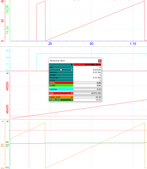
SOD Reverse calculation
!!!Link!!!
|
|
|---|---|
GearCount2D.CAL
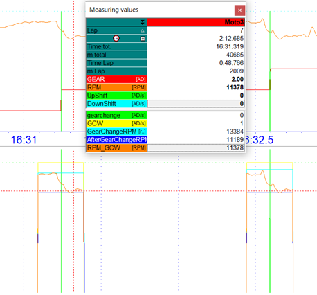
GearCount calculation - Analyzer
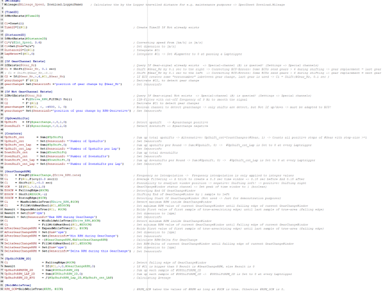
GearCount calculation - CAL file
Important
CAL-file and Template can be found in Moto3-DemoData with DemoUser
In addition to the calculation of the mileage function, the first groups are queried whether a channel is available that has recorded the engaged gear. If no gear channel is available, a gear channel is created via the derivative of the RPM.
This is followed by the Boolean marking of the up- and downshifts and various counters.
From group [GearChange_RPM] on, the actual analysis of the up-switching operations takes place, whereby, at first, with the help of an AVG filter, a 0.3 second GearChangeWindow (GCW) is created around the gear change, in which the rpm during the gear change will be analysed:
C1 = Freq(#GearChange, @Drive_RPM.Rate)
C1 = F(#C1, F(avg(0.3 sec)))
C1 = Shift(#C1, -0.0 sec)
GCW = If(#C1, >, 0, 1, 0)